How to Wire a BTA16 Triac: A Step-by-Step Guide
If you’re looking to control the power supply to a load in an electronic circuit, a BTA16 triac is a popular choice. Triacs are semiconductor devices that can switch high voltage AC loads with a low-voltage DC signal. In this guide, we’ll walk you through the process of wiring a BTA16 triac properly.
Step 1: Gather Your Supplies
Before you begin wiring your BTA16 triac, make sure you have all the necessary supplies on hand. You’ll need the following:
- BTA16 triac
- Heat sink
- Insulating pad
- Wires
- Soldering iron
- Solder
- Multimeter
- Power supply
- Load (such as a lamp or motor)
Step 2: Understand the Pinout
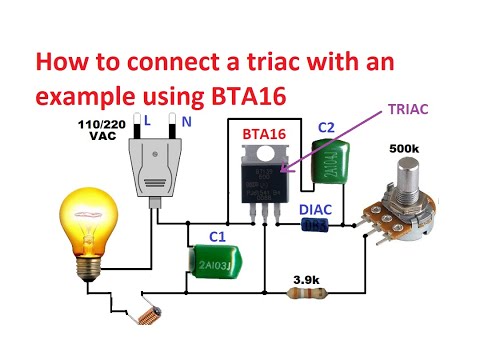
Before you start wiring the BTA16 triac, it’s essential to understand its pinout. The BTA16 triac typically has three pins: MT1, MT2, and gate (G).
MT1 and MT2 are the main terminals of the triac, used to connect the load to the power supply. The gate pin is used to control the triac’s switching action.
Step 3: Connect the Triac to the Load
Start by connecting the MT1 terminal of the BTA16 triac to the AC power supply’s neutral wire. Then, connect the MT2 terminal to the live wire of the power supply. Ensure that you use appropriate wire sizes for the load you’re planning to control.
Step 4: Connect the Gate Pin
Next, connect the gate pin of the BTA16 triac to the output of the control circuit. This is typically done using a low-voltage DC signal, such as from a microcontroller or a timer circuit.
Make sure you use a current-limiting resistor to prevent damage to the triac from excessive gate current.
Step 5: Heat Sink Installation
Triacs can generate heat during operation, so it’s crucial to install a heat sink to dissipate this heat. Place an insulating pad between the BTA16 triac and the heat sink to prevent electrical shorts.
Secure the BTA16 triac and heat sink assembly using screws to ensure proper thermal contact.
Step 6: Test the Wiring
Before applying power to the circuit, use a multimeter to check the continuity of your connections and ensure there are no short circuits. Pay particular attention to the wiring around the BTA16 triac to avoid any mistakes.
Once you’re confident in your wiring, connect the power supply to the circuit and test the triac’s switching capability by applying a control signal to the gate pin.
Step 7: Safety Precautions
When working with high-voltage circuits like those controlled by a BTA16 triac, always follow proper safety precautions. Make sure to disconnect the power supply before making any changes to the wiring, and always use insulated tools to prevent electric shocks.
Remember that incorrect wiring or handling of the BTA16 triac can lead to electric shock or damage to your circuit components.
Conclusion
Wiring a BTA16 triac requires careful attention to detail and understanding of the component’s pinout. By following the steps outlined in this guide, you can safely and effectively wire a BTA16 triac for your electronic projects.
How to Wire a BTA16 Triac: A Step-by-Step Guide
If you’re looking to control the power supply to a load in an electronic circuit, a BTA16 triac is a popular choice. Triacs are semiconductor devices that can switch high voltage AC loads with a low-voltage DC signal. In this guide, we’ll walk you through the process of wiring a BTA16 triac properly.
Step 1: Gather Your Supplies
Before you begin wiring your BTA16 triac, make sure you have all the necessary supplies on hand. You’ll need the following:
- BTA16 triac
- Heat sink
- Insulating pad
- Wires
- Soldering iron
- Solder
- Multimeter
- Power supply
- Load (such as a lamp or motor)
Step 2: Understand the Pinout
Before you start wiring the BTA16 triac, it’s essential to understand its pinout. The BTA16 triac typically has three pins: MT1, MT2, and gate (G).
MT1 and MT2 are the main terminals of the triac, used to connect the load to the power supply. The gate pin is used to control the triac’s switching action.
Step 3: Connect the Triac to the Load
Start by connecting the MT1 terminal of the BTA16 triac to the AC power supply’s neutral wire. Then, connect the MT2 terminal to the live wire of the power supply. Ensure that you use appropriate wire sizes for the load you’re planning to control.
Step 4: Connect the Gate Pin
Next, connect the gate pin of the BTA16 triac to the output of the control circuit. This is typically done using a low-voltage DC signal, such as from a microcontroller or a timer circuit.
Make sure you use a current-limiting resistor to prevent damage to the triac from excessive gate current.
Step 5: Heat Sink Installation
Triacs can generate heat during operation, so it’s crucial to install a heat sink to dissipate this heat. Place an insulating pad between the BTA16 triac and the heat sink to prevent electrical shorts.
Secure the BTA16 triac and heat sink assembly using screws to ensure proper thermal contact.
Step 6: Test the Wiring
Before applying power to the circuit, use a multimeter to check the continuity of your connections and ensure there are no short circuits. Pay particular attention to the wiring around the BTA16 triac to avoid any mistakes.
Once you’re confident in your wiring, connect the power supply to the circuit and test the triac’s switching capability by applying a control signal to the gate pin.
Step 7: Safety Precautions
When working with high-voltage circuits like those controlled by a BTA16 triac, always follow proper safety precautions. Make sure to disconnect the power supply before making any changes to the wiring, and always use insulated tools to prevent electric shocks.
Remember that incorrect wiring or handling of the BTA16 triac can lead to electric shock or damage to your circuit components.
Conclusion
Wiring a BTA16 triac requires careful attention to detail and understanding of the component’s pinout. By following the steps outlined in this guide, you can safely and effectively wire a BTA16 triac for your electronic projects.