How to Use a TL494 PWM Controller
If you’re looking to control power efficiently and effectively in your electronic projects, the TL494 PWM controller is a versatile and popular choice. Whether you’re building a power supply, motor control circuit, or any other application that requires pulse width modulation (PWM), the TL494 can help you achieve precise control over your output voltage or current. In this guide, we’ll walk you through the basics of using this versatile IC.
The TL494 is a pulse width modulator control circuit that is commonly used in power supply circuits. It is designed to provide precision control of switching power supplies, allowing you to adjust the duty cycle of your output waveform to regulate the voltage or current being delivered to your load. The TL494 can be used in a wide range of applications, from simple buck converters to complex multi-output power supplies.
Pin Configuration
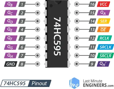
The TL494 comes in an 16-pin dual in-line package (DIP) and features a number of pins that perform specific functions. Here’s a quick overview of the pinout:
- 1. Vref: Reference Voltage Input
- 2. Deadtime Control
- 3. Feedback Input
- 4. Current Sense Input
- 5. Output Control
- 6. Ground
- 7. Error Amplifier Output
- 8. Voltage Reference Output
- 9. Soft-Start
- 10. Output VCC
- 11. Oscillator Timing Capacitor
- 12. Oscillator Timing Resistor
- 13. Output
- 14. Output
- 15. VCC
- 16. VCC
Circuit Design
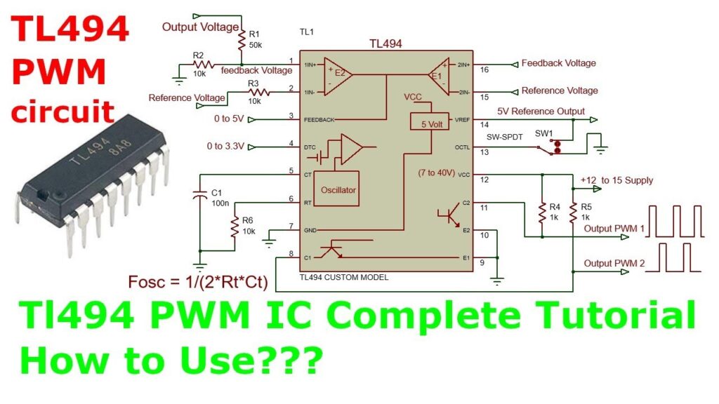
When designing a circuit with the TL494, it’s important to consider the specific requirements of your application. The TL494 can be configured to operate in a variety of modes, including voltage mode control and current mode control. Whether you’re building a power supply, a motor control circuit, or any other application that requires PWM control, the TL494 can be adapted to meet your needs.
To get started with the TL494, you’ll need to connect the various input and output pins to their respective components in your circuit. This may include connecting the voltage reference pin to a stable voltage source, the feedback pin to a voltage divider, and the error amplifier output to the driver circuit for your power transistors.
It’s also important to consider the frequency of operation and the duty cycle of your PWM signal when using the TL494. By adjusting the timing components in the oscillator circuit, you can set the desired frequency of operation, while the deadtime control pin allows you to adjust the duty cycle of your output waveform.
Applications
The TL494 is a versatile PWM controller that can be used in a wide range of applications, including:
- Switch-mode power supplies
- DC-DC converters
- Inverters
- Motor control circuits
- Battery chargers
- LED drivers
- Solar inverters
By understanding how to use the TL494 PWM controller in your circuits, you can take advantage of its flexibility and precision control to achieve optimal performance in your electronic projects.
Whether you’re a beginner or an experienced electronics enthusiast, the TL494 is a powerful tool that can help you take your projects to the next level. Experiment with different circuit configurations, explore the various operating modes, and discover how the TL494 PWM controller can enhance the performance of your power electronics projects.
How to Use a TL494 PWM Controller
If you’re looking to control power efficiently and effectively in your electronic projects, the TL494 PWM controller is a versatile and popular choice. Whether you’re building a power supply, motor control circuit, or any other application that requires pulse width modulation (PWM), the TL494 can help you achieve precise control over your output voltage or current. In this guide, we’ll walk you through the basics of using this versatile IC.
The TL494 is a pulse width modulator control circuit that is commonly used in power supply circuits. It is designed to provide precision control of switching power supplies, allowing you to adjust the duty cycle of your output waveform to regulate the voltage or current being delivered to your load. The TL494 can be used in a wide range of applications, from simple buck converters to complex multi-output power supplies.
Pin Configuration
The TL494 comes in an 16-pin dual in-line package (DIP) and features a number of pins that perform specific functions. Here’s a quick overview of the pinout:
- 1. Vref: Reference Voltage Input
- 2. Deadtime Control
- 3. Feedback Input
- 4. Current Sense Input
- 5. Output Control
- 6. Ground
- 7. Error Amplifier Output
- 8. Voltage Reference Output
- 9. Soft-Start
- 10. Output VCC
- 11. Oscillator Timing Capacitor
- 12. Oscillator Timing Resistor
- 13. Output
- 14. Output
- 15. VCC
- 16. VCC
Circuit Design
When designing a circuit with the TL494, it’s important to consider the specific requirements of your application. The TL494 can be configured to operate in a variety of modes, including voltage mode control and current mode control. Whether you’re building a power supply, a motor control circuit, or any other application that requires PWM control, the TL494 can be adapted to meet your needs.
To get started with the TL494, you’ll need to connect the various input and output pins to their respective components in your circuit. This may include connecting the voltage reference pin to a stable voltage source, the feedback pin to a voltage divider, and the error amplifier output to the driver circuit for your power transistors.
It’s also important to consider the frequency of operation and the duty cycle of your PWM signal when using the TL494. By adjusting the timing components in the oscillator circuit, you can set the desired frequency of operation, while the deadtime control pin allows you to adjust the duty cycle of your output waveform.
Applications
The TL494 is a versatile PWM controller that can be used in a wide range of applications, including:
- Switch-mode power supplies
- DC-DC converters
- Inverters
- Motor control circuits
- Battery chargers
- LED drivers
- Solar inverters
By understanding how to use the TL494 PWM controller in your circuits, you can take advantage of its flexibility and precision control to achieve optimal performance in your electronic projects.
Whether you’re a beginner or an experienced electronics enthusiast, the TL494 is a powerful tool that can help you take your projects to the next level. Experiment with different circuit configurations, explore the various operating modes, and discover how the TL494 PWM controller can enhance the performance of your power electronics projects.