How to Use a SN74HC165 Shift Register
Shift registers are handy components for expanding the number of inputs or outputs on a microcontroller. The SN74HC165 shift register is a popular choice due to its simplicity and ease of use. In this article, we will show you how to use a SN74HC165 shift register with your microcontroller for increased input capacity.
What is a SN74HC165 Shift Register?
The SN74HC165 is an 8-bit parallel-load shift register. It allows you to expand the number of input pins on your microcontroller without taking up a lot of pins. It works by shifting data serially into the shift register and then latching it in parallel for quick and easy retrieval.
Pinout of the SN74HC165 Shift Register
The SN74HC165 shift register has the following pinout:
- Vcc – Power supply voltage
- GND – Ground
- Parallel Load (PL) – Load data in parallel
- Serial Data In (DS) – Input data serially
- Serial Clock (SH_CP) – Clock signal for shifting data
- Parallel Data Out (QH) – Parallel output data
- Clock Inhibit (SH_CP) – Clock enable/disable
Connecting the SN74HC165 Shift Register
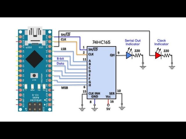
To use the SN74HC165 shift register, you will need to connect it to your microcontroller. Here is a basic connection diagram:
- Vcc to power supply voltage
- GND to ground
- Parallel Load (PL) to a digital pin on your microcontroller
- Serial Data In (DS) to a digital pin on your microcontroller
- Serial Clock (SH_CP) to a digital pin on your microcontroller
- Parallel Data Out (QH) to your microcontroller input
- Clock Inhibit (SH_CP) to a digital pin on your microcontroller
Using the SN74HC165 Shift Register
Once you have connected the SN74HC165 shift register to your microcontroller, you can start using it to expand your input capacity. Here is a basic example of how to read data from the shift register:
#include <SPI.h>

#define DS 2
#define SH_CP 3
#define PL 4

void setup() {
  pinMode(DS, INPUT);
  pinMode(SH_CP, OUTPUT);
  pinMode(PL, OUTPUT);
}

void loop() {
  digitalWrite(PL, HIGH);
  digitalWrite(PL, LOW);
  byte data = 0;

  for (int i = 0; i < 8; i++) {
    digitalWrite(SH_CP, HIGH);
    bitWrite(data, 7 - i, digitalRead(DS));
    digitalWrite(SH_CP, LOW);
  }

  Serial.println(data, BIN);
}
In this example, we are using the Arduino SPI library to read data from the shift register. We first set the parallel load pin high and then low to start shifting data. We then read each bit of data serially and store it in a byte variable. Finally, we print out the binary representation of the data.
Conclusion
The SN74HC165 shift register is a useful component for expanding the input capacity of your microcontroller. By following the steps outlined in this article, you can easily add more inputs to your projects without using up all of your digital pins. Experiment with different configurations and see how you can make the most out of the SN74HC165 shift register in your projects!
How to Use a SN74HC165 Shift Register
Shift registers are handy components for expanding the number of inputs or outputs on a microcontroller. The SN74HC165 shift register is a popular choice due to its simplicity and ease of use. In this article, we will show you how to use a SN74HC165 shift register with your microcontroller for increased input capacity.
What is a SN74HC165 Shift Register?
The SN74HC165 is an 8-bit parallel-load shift register. It allows you to expand the number of input pins on your microcontroller without taking up a lot of pins. It works by shifting data serially into the shift register and then latching it in parallel for quick and easy retrieval.
Pinout of the SN74HC165 Shift Register
The SN74HC165 shift register has the following pinout:
- Vcc – Power supply voltage
- GND – Ground
- Parallel Load (PL) – Load data in parallel
- Serial Data In (DS) – Input data serially
- Serial Clock (SH_CP) – Clock signal for shifting data
- Parallel Data Out (QH) – Parallel output data
- Clock Inhibit (SH_CP) – Clock enable/disable
Connecting the SN74HC165 Shift Register
To use the SN74HC165 shift register, you will need to connect it to your microcontroller. Here is a basic connection diagram:
- Vcc to power supply voltage
- GND to ground
- Parallel Load (PL) to a digital pin on your microcontroller
- Serial Data In (DS) to a digital pin on your microcontroller
- Serial Clock (SH_CP) to a digital pin on your microcontroller
- Parallel Data Out (QH) to your microcontroller input
- Clock Inhibit (SH_CP) to a digital pin on your microcontroller
Using the SN74HC165 Shift Register
Once you have connected the SN74HC165 shift register to your microcontroller, you can start using it to expand your input capacity. Here is a basic example of how to read data from the shift register:
#include <SPI.h>

#define DS 2
#define SH_CP 3
#define PL 4

void setup() {
  pinMode(DS, INPUT);
  pinMode(SH_CP, OUTPUT);
  pinMode(PL, OUTPUT);
}

void loop() {
  digitalWrite(PL, HIGH);
  digitalWrite(PL, LOW);
  byte data = 0;

  for (int i = 0; i < 8; i++) {
    digitalWrite(SH_CP, HIGH);
    bitWrite(data, 7 - i, digitalRead(DS));
    digitalWrite(SH_CP, LOW);
  }

  Serial.println(data, BIN);
}
In this example, we are using the Arduino SPI library to read data from the shift register. We first set the parallel load pin high and then low to start shifting data. We then read each bit of data serially and store it in a byte variable. Finally, we print out the binary representation of the data.
Conclusion
The SN74HC165 shift register is a useful component for expanding the input capacity of your microcontroller. By following the steps outlined in this article, you can easily add more inputs to your projects without using up all of your digital pins. Experiment with different configurations and see how you can make the most out of the SN74HC165 shift register in your projects!