How to design an IR sensor circuit?
Designing an infrared (IR) sensor circuit can be a fun and rewarding project for both beginners and experienced electronics enthusiasts. IR sensors are versatile devices that can be used in a wide range of applications such as proximity sensing, object detection, and remote control systems. In this article, we will guide you through the process of designing a simple IR sensor circuit from scratch.
Step 1: Choose the right components
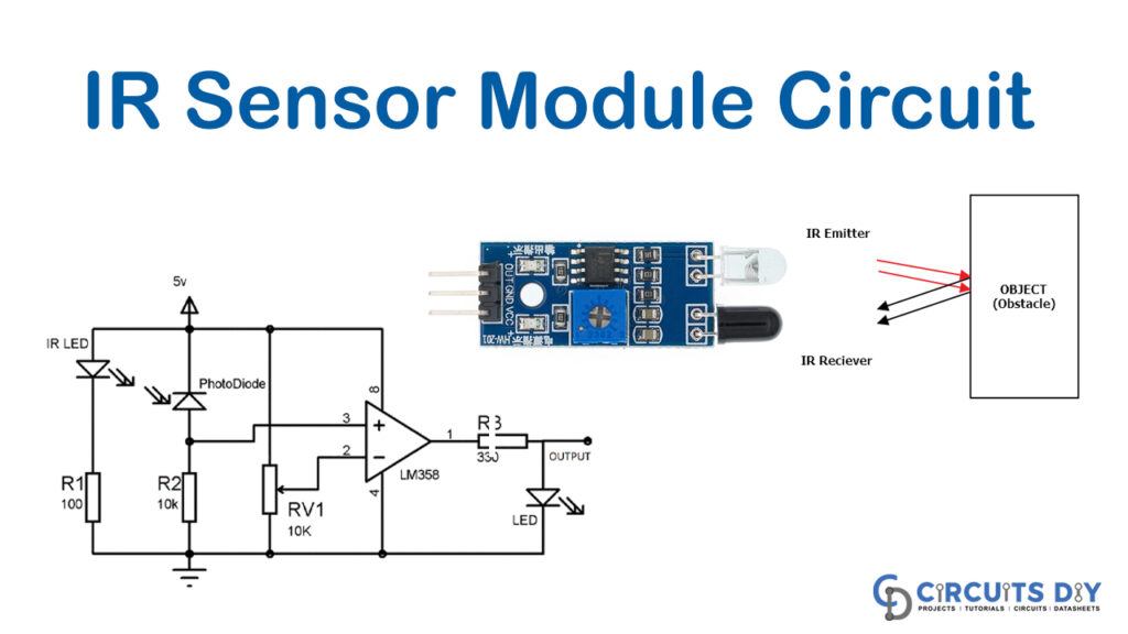
The first step in designing an IR sensor circuit is to choose the right components. You will need an IR LED, a photodiode or phototransistor, a resistor, and a power source. The IR LED emits infrared light, while the photodiode or phototransistor detects this light and produces a corresponding electrical signal. The resistor is used to limit the current flowing through the IR LED.
Step 2: Determine the circuit configuration
Next, you need to determine the circuit configuration for your IR sensor. There are two common configurations used in IR sensor circuits: active-high and active-low. In an active-high configuration, the output signal is high when the IR light is detected, while in an active-low configuration, the output signal is low when the IR light is detected.
Step 3: Design the circuit schematic
Now it’s time to design the circuit schematic for your IR sensor. You can use a software tool such as Eagle or KiCad to create a schematic diagram of the circuit. Make sure to include all the components in the diagram, along with their connections and values. Pay special attention to the polarity of the IR LED and the photodiode or phototransistor.
Step 4: Calculate the resistor value
Before assembling the circuit, you need to calculate the value of the resistor that will be used to limit the current flowing through the IR LED. You can use Ohm’s Law to calculate the resistor value based on the forward voltage and forward current of the IR LED. Make sure to choose a resistor with the closest standard value.
Step 5: Assemble the circuit
Once you have all the components and the circuit schematic ready, it’s time to assemble the IR sensor circuit. Place the components on a breadboard or a PCB according to the schematic diagram. Make sure to double-check all the connections and polarities before powering up the circuit.
Step 6: Test the circuit
After assembling the circuit, it’s important to test it to make sure it’s working correctly. You can test the IR sensor circuit by using a remote control or any other IR source. When the IR light is detected, the output signal of the circuit should change accordingly. You can use an oscilloscope or a multimeter to measure the output voltage.
Step 7: Troubleshooting
If the IR sensor circuit is not working as expected, you may need to troubleshoot the circuit. Check the connections, polarities, and component values to make sure everything is correct. You can also try replacing the components one by one to identify any faulty parts. Sometimes, a simple mistake such as a loose connection can cause the circuit to malfunction.
Conclusion
Designing an IR sensor circuit can be a challenging but rewarding experience. By following the steps outlined in this article, you can create a functional IR sensor circuit for your projects. Remember to choose the right components, determine the circuit configuration, design the circuit schematic, calculate the resistor value, assemble the circuit, test the circuit, and troubleshoot any issues that may arise. With practice and patience, you can master the art of designing IR sensor circuits.
How to design an IR sensor circuit?
Designing an infrared (IR) sensor circuit can be a fun and rewarding project for both beginners and experienced electronics enthusiasts. IR sensors are versatile devices that can be used in a wide range of applications such as proximity sensing, object detection, and remote control systems. In this article, we will guide you through the process of designing a simple IR sensor circuit from scratch.
Step 1: Choose the right components
The first step in designing an IR sensor circuit is to choose the right components. You will need an IR LED, a photodiode or phototransistor, a resistor, and a power source. The IR LED emits infrared light, while the photodiode or phototransistor detects this light and produces a corresponding electrical signal. The resistor is used to limit the current flowing through the IR LED.
Step 2: Determine the circuit configuration
Next, you need to determine the circuit configuration for your IR sensor. There are two common configurations used in IR sensor circuits: active-high and active-low. In an active-high configuration, the output signal is high when the IR light is detected, while in an active-low configuration, the output signal is low when the IR light is detected.
Step 3: Design the circuit schematic
Now it’s time to design the circuit schematic for your IR sensor. You can use a software tool such as Eagle or KiCad to create a schematic diagram of the circuit. Make sure to include all the components in the diagram, along with their connections and values. Pay special attention to the polarity of the IR LED and the photodiode or phototransistor.
Step 4: Calculate the resistor value
Before assembling the circuit, you need to calculate the value of the resistor that will be used to limit the current flowing through the IR LED. You can use Ohm’s Law to calculate the resistor value based on the forward voltage and forward current of the IR LED. Make sure to choose a resistor with the closest standard value.
Step 5: Assemble the circuit
Once you have all the components and the circuit schematic ready, it’s time to assemble the IR sensor circuit. Place the components on a breadboard or a PCB according to the schematic diagram. Make sure to double-check all the connections and polarities before powering up the circuit.
Step 6: Test the circuit
After assembling the circuit, it’s important to test it to make sure it’s working correctly. You can test the IR sensor circuit by using a remote control or any other IR source. When the IR light is detected, the output signal of the circuit should change accordingly. You can use an oscilloscope or a multimeter to measure the output voltage.
Step 7: Troubleshooting
If the IR sensor circuit is not working as expected, you may need to troubleshoot the circuit. Check the connections, polarities, and component values to make sure everything is correct. You can also try replacing the components one by one to identify any faulty parts. Sometimes, a simple mistake such as a loose connection can cause the circuit to malfunction.
Conclusion
Designing an IR sensor circuit can be a challenging but rewarding experience. By following the steps outlined in this article, you can create a functional IR sensor circuit for your projects. Remember to choose the right components, determine the circuit configuration, design the circuit schematic, calculate the resistor value, assemble the circuit, test the circuit, and troubleshoot any issues that may arise. With practice and patience, you can master the art of designing IR sensor circuits.