How to Create a Vibration Sensor Circuit
Have you ever wanted to create a vibration sensor circuit but didn’t know where to start? In this article, we will guide you through the process of building your own vibration sensor circuit from scratch. Whether you are a beginner or an experienced electronics enthusiast, this step-by-step tutorial will help you understand the basics of sensor technology and how to implement it in your projects.
A vibration sensor circuit is a valuable tool for monitoring and detecting vibrations in various applications, such as earthquake detection, machine condition monitoring, and motion detection. By detecting vibrations, you can trigger alarms, control systems, or record data for analysis.
Components Needed
- Vibration sensor module (such as SW-420)
- Arduino microcontroller board
- Resistors
- LED
- Breadboard
- Jumper wires
Step 1: Understand How a Vibration Sensor Works
Before we start building the circuit, let’s understand how a vibration sensor works. A vibration sensor typically consists of a spring-mounted mass that moves in response to vibrations. When the mass moves, it creates an electrical signal that can be detected by the circuit. The sensor module we will use in this tutorial, the SW-420, has a built-in comparator that converts the analog signal into a digital signal when a certain vibration threshold is reached.
Now that you have a basic understanding of how a vibration sensor works, let’s move on to the next step.
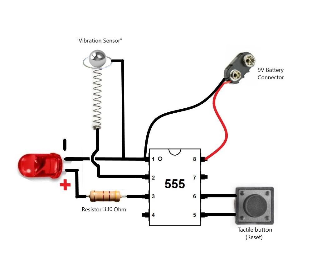
Step 2: Connect the Components
Start by connecting the components on the breadboard. Connect the vibration sensor module to the Arduino board using jumper wires. Make sure to connect the signal pin of the sensor module to a digital input pin on the Arduino board. Connect an LED to the Arduino board to indicate when vibrations are detected.
Next, connect the resistors to the circuit to limit the current flowing through the LED. The resistor values will depend on the specifications of the LED you are using, so make sure to check the datasheet for the correct values.
Once you have connected all the components, you are ready to move on to the next step.
Step 3: Write the Arduino Code
Open the Arduino IDE and write the code to read the sensor module’s output and turn on the LED when vibrations are detected. You can use the digitalRead() function to read the signal from the sensor module and the digitalWrite() function to control the LED.
Upload the code to the Arduino board and test the circuit by gently tapping the sensor module. The LED should turn on when vibrations are detected.
Step 4: Test the Circuit
After uploading the code to the Arduino board, test the circuit to ensure that it is functioning correctly. Try varying the intensity of the vibrations to see how the sensor module responds. You can also adjust the vibration threshold on the sensor module to trigger the LED at different levels of vibration.
Step 5: Further Enhancements
Once you have successfully built and tested the basic vibration sensor circuit, you can explore additional features and enhancements. For example, you can add an LCD display to show real-time vibration data, or connect the Arduino board to a computer to log the vibration data for analysis.
By experimenting with different components and programming techniques, you can customize the vibration sensor circuit to suit your specific application requirements.
Conclusion
Building a vibration sensor circuit can be a rewarding and educational experience. By following this tutorial, you have learned how to create a basic vibration sensor circuit using an Arduino board and a vibration sensor module. You can now apply this knowledge to more advanced projects and explore the endless possibilities of sensor technology.
How to Create a Vibration Sensor Circuit
Have you ever wanted to create a vibration sensor circuit but didn’t know where to start? In this article, we will guide you through the process of building your own vibration sensor circuit from scratch. Whether you are a beginner or an experienced electronics enthusiast, this step-by-step tutorial will help you understand the basics of sensor technology and how to implement it in your projects.
A vibration sensor circuit is a valuable tool for monitoring and detecting vibrations in various applications, such as earthquake detection, machine condition monitoring, and motion detection. By detecting vibrations, you can trigger alarms, control systems, or record data for analysis.
Components Needed
- Vibration sensor module (such as SW-420)
- Arduino microcontroller board
- Resistors
- LED
- Breadboard
- Jumper wires
Step 1: Understand How a Vibration Sensor Works
Before we start building the circuit, let’s understand how a vibration sensor works. A vibration sensor typically consists of a spring-mounted mass that moves in response to vibrations. When the mass moves, it creates an electrical signal that can be detected by the circuit. The sensor module we will use in this tutorial, the SW-420, has a built-in comparator that converts the analog signal into a digital signal when a certain vibration threshold is reached.
Now that you have a basic understanding of how a vibration sensor works, let’s move on to the next step.
Step 2: Connect the Components
Start by connecting the components on the breadboard. Connect the vibration sensor module to the Arduino board using jumper wires. Make sure to connect the signal pin of the sensor module to a digital input pin on the Arduino board. Connect an LED to the Arduino board to indicate when vibrations are detected.
Next, connect the resistors to the circuit to limit the current flowing through the LED. The resistor values will depend on the specifications of the LED you are using, so make sure to check the datasheet for the correct values.
Once you have connected all the components, you are ready to move on to the next step.
Step 3: Write the Arduino Code
Open the Arduino IDE and write the code to read the sensor module’s output and turn on the LED when vibrations are detected. You can use the digitalRead() function to read the signal from the sensor module and the digitalWrite() function to control the LED.
Upload the code to the Arduino board and test the circuit by gently tapping the sensor module. The LED should turn on when vibrations are detected.
Step 4: Test the Circuit
After uploading the code to the Arduino board, test the circuit to ensure that it is functioning correctly. Try varying the intensity of the vibrations to see how the sensor module responds. You can also adjust the vibration threshold on the sensor module to trigger the LED at different levels of vibration.
Step 5: Further Enhancements
Once you have successfully built and tested the basic vibration sensor circuit, you can explore additional features and enhancements. For example, you can add an LCD display to show real-time vibration data, or connect the Arduino board to a computer to log the vibration data for analysis.
By experimenting with different components and programming techniques, you can customize the vibration sensor circuit to suit your specific application requirements.
Conclusion
Building a vibration sensor circuit can be a rewarding and educational experience. By following this tutorial, you have learned how to create a basic vibration sensor circuit using an Arduino board and a vibration sensor module. You can now apply this knowledge to more advanced projects and explore the endless possibilities of sensor technology.