How to Build a LED Chaser Circuit
LED chaser circuits are a fun and visually appealing way to add a bit of flair to your electronics projects. In this article, we will walk you through how to build a simple LED chaser circuit using basic components.
Materials Needed
- 555 Timer IC
- 10 LEDs
- 100kΩ resistor
- 10kΩ resistor
- 10µF capacitor
- Breadboard
- Jumper wires
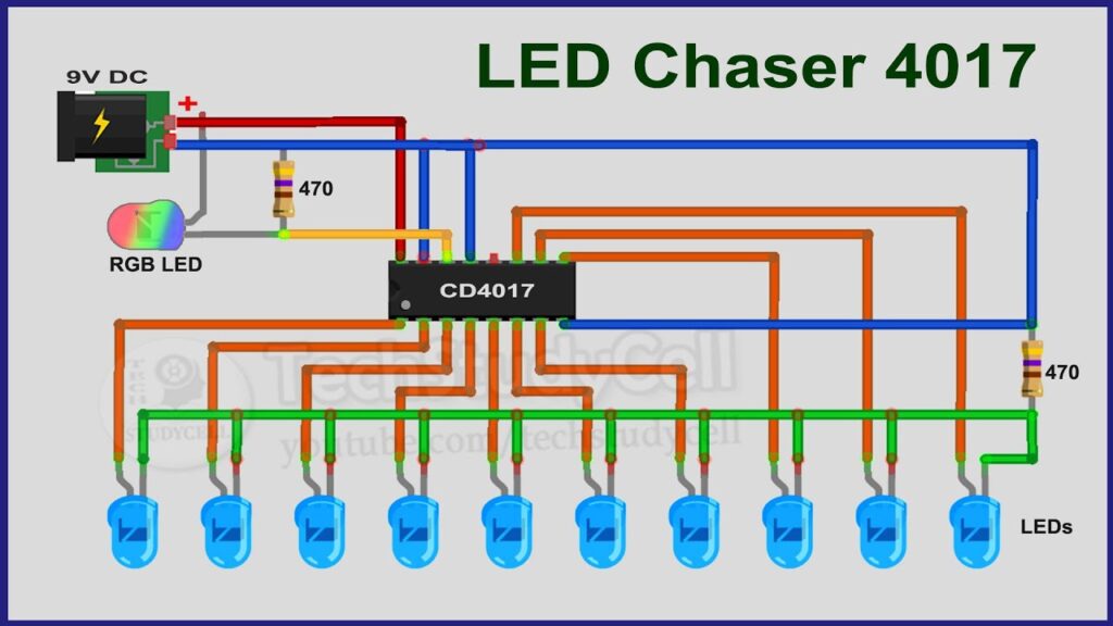
Step 1: Circuit Diagram
Start by setting up the circuit as shown in the diagram below:

Step 2: Building the Circuit
Now, let’s walk through the process of building the LED chaser circuit:
- Insert the 555 Timer IC into the breadboard.
- Connect pin 4 (reset) to pin 8 (VCC) and pin 1 (ground) to pin 5 (control voltage).
- Connect pin 2 (trigger) to pin 6 (threshold) through a 100kΩ resistor.
- Connect pin 6 (threshold) to pin 7 (discharge).
- Connect pin 3 (output) to the positive rail of the breadboard through a 10kΩ resistor and a 10µF capacitor in parallel.
- Connect the cathode of each LED to pin 3 (output) through a current-limiting resistor and the anode to the negative rail of the breadboard.
- Connect the negative rail of the breadboard to pin 1 (ground).
Step 3: Testing the Circuit
Apply power to the breadboard and watch as the LEDs light up in a chasing pattern. You can adjust the speed of the chasing effect by changing the values of the resistors and capacitor.
Conclusion
Congratulations! You have successfully built a LED chaser circuit. Experiment with different LED configurations and speeds to create your own unique light show.
Have fun tinkering and exploring the world of electronics with this simple and entertaining project.
How to Build a LED Chaser Circuit
LED chaser circuits are a fun and visually appealing way to add a bit of flair to your electronics projects. In this article, we will walk you through how to build a simple LED chaser circuit using basic components.
Materials Needed
- 555 Timer IC
- 10 LEDs
- 100kΩ resistor
- 10kΩ resistor
- 10µF capacitor
- Breadboard
- Jumper wires
Step 1: Circuit Diagram
Start by setting up the circuit as shown in the diagram below:
Step 2: Building the Circuit
Now, let’s walk through the process of building the LED chaser circuit:
- Insert the 555 Timer IC into the breadboard.
- Connect pin 4 (reset) to pin 8 (VCC) and pin 1 (ground) to pin 5 (control voltage).
- Connect pin 2 (trigger) to pin 6 (threshold) through a 100kΩ resistor.
- Connect pin 6 (threshold) to pin 7 (discharge).
- Connect pin 3 (output) to the positive rail of the breadboard through a 10kΩ resistor and a 10µF capacitor in parallel.
- Connect the cathode of each LED to pin 3 (output) through a current-limiting resistor and the anode to the negative rail of the breadboard.
- Connect the negative rail of the breadboard to pin 1 (ground).
Step 3: Testing the Circuit
Apply power to the breadboard and watch as the LEDs light up in a chasing pattern. You can adjust the speed of the chasing effect by changing the values of the resistors and capacitor.
Conclusion
Congratulations! You have successfully built a LED chaser circuit. Experiment with different LED configurations and speeds to create your own unique light show.
Have fun tinkering and exploring the world of electronics with this simple and entertaining project.