Best Way to Design a Low-Pass Filter Circuit
Low-pass filters are essential components in electronic circuits, allowing only low-frequency signals to pass through while attenuating higher frequencies. They are commonly used in audio applications, power supplies, and communication systems to remove unwanted high-frequency noise.
Designing a low-pass filter circuit requires careful consideration of the desired cutoff frequency, filter order, and component values. In this article, we will discuss the best way to design a low-pass filter circuit for your specific application.
1. Determine the Cutoff Frequency
The cutoff frequency is the frequency at which the filter begins to attenuate the input signal. It is typically denoted as ƒc and is a crucial parameter in designing a low-pass filter circuit. To determine the cutoff frequency, you need to consider the bandwidth requirements of your system and the frequency range of the input signal.
Once you have determined the cutoff frequency, you can move on to selecting the appropriate filter topology.
2. Choose the Filter Topology
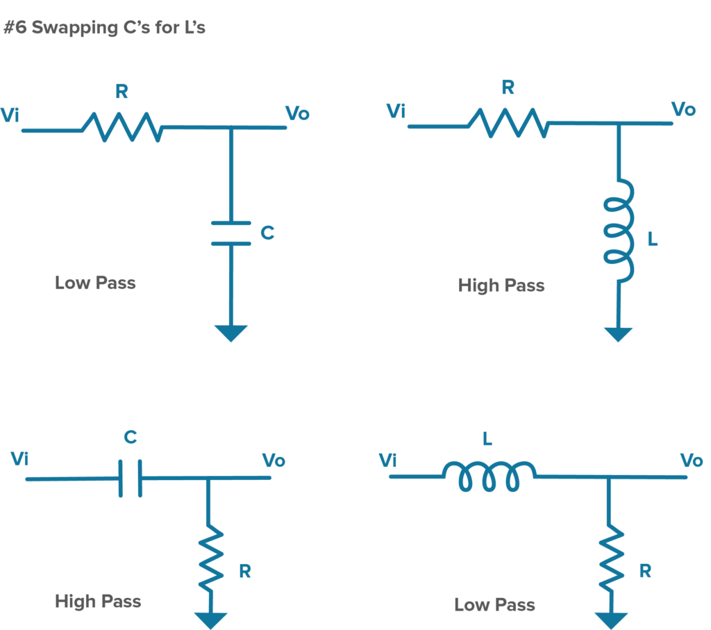
There are several filter topologies to choose from when designing a low-pass filter circuit, including passive RC filters, active filters, and Sallen-Key filters. Each topology has its advantages and disadvantages, so it is essential to select the one that best suits your application requirements.
Passive RC filters are simple and cost-effective but may have limited performance in terms of bandwidth and attenuation. Active filters, on the other hand, use operational amplifiers to achieve higher performance but are more complex and require power supplies.
The Sallen-Key filter is a popular choice for low-pass filter design, offering a good balance of performance and complexity. It provides high attenuation at the cutoff frequency and allows for easy tuning of the filter parameters.
3. Calculate Component Values
Once you have chosen the filter topology, you need to calculate the component values for the circuit. The values of the resistors and capacitors in the filter determine the cutoff frequency, filter order, and attenuation characteristics.
For passive RC filters, the cutoff frequency (ƒc) and the component values can be calculated using the following formulas:
- Resistor: R = 1 / (2πƒcC)
- Capacitor: C = 1 / (2πƒcR)
For active filters, the component values depend on the filter topology and the desired performance specifications. Online calculators and simulation software can help in determining the values of the resistors and capacitors for the chosen filter topology.
4. Simulate the Filter Circuit
Before building the filter circuit, it is essential to simulate it using circuit simulation software. This will help in verifying the performance of the filter, analyzing its frequency response, and predicting any potential issues that may arise during testing.
Most circuit simulation software tools allow you to input the component values, simulate the circuit, and analyze the output waveform. This step is crucial in fine-tuning the filter parameters and ensuring that it meets the desired specifications.
5. Build and Test the Filter Circuit
Once you have simulated the filter circuit and are satisfied with its performance, you can proceed to build the actual circuit. Use high-quality components and follow the schematic closely to ensure proper operation of the filter.
After building the circuit, it is essential to test it thoroughly using a signal generator and an oscilloscope. Verify that the filter attenuates high-frequency signals as expected and does not introduce any distortion or noise into the output signal.
If the filter does not meet the desired specifications, you may need to go back to the simulation step and fine-tune the component values or consider changing the filter topology.
6. Conclusion
Designing a low-pass filter circuit requires careful planning, calculation, and testing to ensure optimal performance. By following the steps outlined in this article, you can design a low-pass filter circuit that meets your specific application requirements and provides reliable filtering of unwanted high-frequency signals.
Remember to consider the cutoff frequency, choose the appropriate filter topology, calculate the component values, simulate the circuit, and test the filter thoroughly before integrating it into your system. With the right design approach and attention to detail, you can create a high-quality low-pass filter circuit for your electronic applications.
Best Way to Design a Low-Pass Filter Circuit
Low-pass filters are essential components in electronic circuits, allowing only low-frequency signals to pass through while attenuating higher frequencies. They are commonly used in audio applications, power supplies, and communication systems to remove unwanted high-frequency noise.
Designing a low-pass filter circuit requires careful consideration of the desired cutoff frequency, filter order, and component values. In this article, we will discuss the best way to design a low-pass filter circuit for your specific application.
1. Determine the Cutoff Frequency
The cutoff frequency is the frequency at which the filter begins to attenuate the input signal. It is typically denoted as ƒc and is a crucial parameter in designing a low-pass filter circuit. To determine the cutoff frequency, you need to consider the bandwidth requirements of your system and the frequency range of the input signal.
Once you have determined the cutoff frequency, you can move on to selecting the appropriate filter topology.
2. Choose the Filter Topology
There are several filter topologies to choose from when designing a low-pass filter circuit, including passive RC filters, active filters, and Sallen-Key filters. Each topology has its advantages and disadvantages, so it is essential to select the one that best suits your application requirements.
Passive RC filters are simple and cost-effective but may have limited performance in terms of bandwidth and attenuation. Active filters, on the other hand, use operational amplifiers to achieve higher performance but are more complex and require power supplies.
The Sallen-Key filter is a popular choice for low-pass filter design, offering a good balance of performance and complexity. It provides high attenuation at the cutoff frequency and allows for easy tuning of the filter parameters.
3. Calculate Component Values
Once you have chosen the filter topology, you need to calculate the component values for the circuit. The values of the resistors and capacitors in the filter determine the cutoff frequency, filter order, and attenuation characteristics.
For passive RC filters, the cutoff frequency (ƒc) and the component values can be calculated using the following formulas:
- Resistor: R = 1 / (2πƒcC)
- Capacitor: C = 1 / (2πƒcR)
For active filters, the component values depend on the filter topology and the desired performance specifications. Online calculators and simulation software can help in determining the values of the resistors and capacitors for the chosen filter topology.
4. Simulate the Filter Circuit
Before building the filter circuit, it is essential to simulate it using circuit simulation software. This will help in verifying the performance of the filter, analyzing its frequency response, and predicting any potential issues that may arise during testing.
Most circuit simulation software tools allow you to input the component values, simulate the circuit, and analyze the output waveform. This step is crucial in fine-tuning the filter parameters and ensuring that it meets the desired specifications.
5. Build and Test the Filter Circuit
Once you have simulated the filter circuit and are satisfied with its performance, you can proceed to build the actual circuit. Use high-quality components and follow the schematic closely to ensure proper operation of the filter.
After building the circuit, it is essential to test it thoroughly using a signal generator and an oscilloscope. Verify that the filter attenuates high-frequency signals as expected and does not introduce any distortion or noise into the output signal.
If the filter does not meet the desired specifications, you may need to go back to the simulation step and fine-tune the component values or consider changing the filter topology.
6. Conclusion
Designing a low-pass filter circuit requires careful planning, calculation, and testing to ensure optimal performance. By following the steps outlined in this article, you can design a low-pass filter circuit that meets your specific application requirements and provides reliable filtering of unwanted high-frequency signals.
Remember to consider the cutoff frequency, choose the appropriate filter topology, calculate the component values, simulate the circuit, and test the filter thoroughly before integrating it into your system. With the right design approach and attention to detail, you can create a high-quality low-pass filter circuit for your electronic applications.