How to Design a 100W Inverter Circuit
Are you looking to design a 100W inverter circuit? Inverters are essential devices that convert direct current (DC) into alternating current (AC), making them extremely useful for powering electronic devices when an AC power source is not available. In this article, we will guide you through the process of designing a 100W inverter circuit from scratch.
Step 1: Determine Power Requirements
The first step in designing an inverter circuit is to determine the power requirements of the devices you intend to power. In this case, we are aiming for a 100W output, so we need to ensure that our circuit can handle this power load efficiently. Make a list of all the devices you plan to power with the inverter and add up their power consumption in watts.
Step 2: Select Components
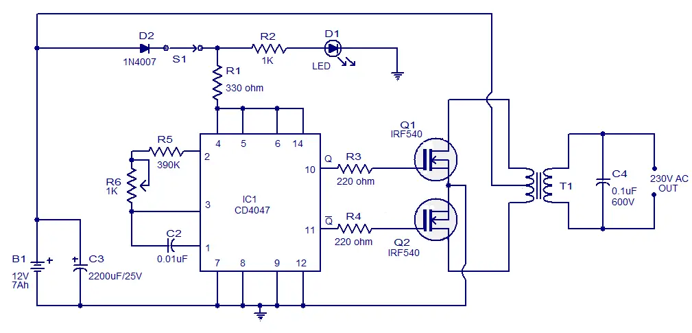
Once you have determined the power requirements, the next step is to select the components needed for the inverter circuit. Some key components you will need include:
- Transformers
- MOSFETs
- Diodes
- Capacitors
- Resistors
- Integrated circuits
Make sure to choose components that can handle the power output and are compatible with each other. It is also important to consider the efficiency and reliability of the components when designing the circuit.
Step 3: Circuit Design
Now that you have selected the components, it’s time to design the circuit. Start by creating a schematic diagram of the inverter circuit, showing how each component is connected. Pay attention to the input and output connections, as well as the placement of components to ensure optimal performance.
Consider factors such as voltage regulation, frequency control, and overload protection when designing the circuit. This will help ensure that your inverter operates efficiently and safely.
Step 4: Build the Circuit
With the circuit design complete, it’s time to build the inverter circuit. Gather all the components and carefully solder them onto a prototyping board following the schematic diagram you created. Double-check all connections to avoid any errors that could affect the circuit’s performance.
Once the circuit is built, test it with a power supply and load to ensure that it functions as intended. Make any necessary adjustments to the circuit to improve its efficiency and performance.
Step 5: Testing and Optimization
After building the circuit, it’s essential to test its performance and make any necessary optimizations. Use a multimeter to measure the voltage and current outputs of the inverter under different loads to ensure that it meets the required specifications.
Optimize the circuit by tweaking component values or adjusting connections to improve efficiency and reliability. Perform thorough testing to ensure that the inverter operates safely and consistently under various conditions.
Step 6: Finalize the Design
Once you are satisfied with the performance of the inverter circuit, finalize the design by creating a permanent PCB layout. Transfer the components to a printed circuit board using proper layout techniques to ensure a clean and compact design.
After soldering all components onto the PCB, test the inverter once again to verify that everything is functioning correctly. Make any final adjustments as needed to perfect the circuit before sealing the PCB in an enclosure for protection.
Conclusion
Designing a 100W inverter circuit requires careful planning, component selection, and testing to ensure optimal performance. By following the steps outlined in this article and paying attention to detail, you can create a reliable and efficient inverter for powering your electronic devices.
Was this helpful?
0 / 0