How to use a P-channel MOSFET for power switching?
Power switching is an essential part of electronic circuit design, and using a P-channel MOSFET can be an effective way to control the flow of power. In this article, we’ll discuss how to properly use a P-channel MOSFET for power switching applications.
First, let’s understand what a P-channel MOSFET is. A MOSFET, which stands for Metal-Oxide-Semiconductor Field-Effect Transistor, is a type of semiconductor device commonly used for switching electronic signals. The P-channel MOSFET is one of the two main types of MOSFETs, with the other being the N-channel MOSFET. The P-channel MOSFET is often used in applications where the load is connected to the power supply, making it ideal for power switching.
Step 1: Understanding the Pinout
Before using a P-channel MOSFET for power switching, it’s important to understand the pinout of the device. A typical P-channel MOSFET has three pins: the source, gate, and drain. The source pin is connected to the positive power supply voltage, while the drain pin is connected to the load. The gate pin is used to control the switching of the MOSFET.
Step 2: Connection Diagram
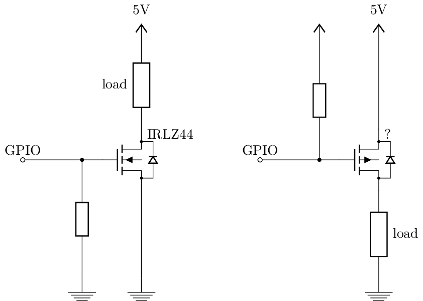
When using a P-channel MOSFET for power switching, the connection diagram is crucial for proper operation. The source pin should be connected to the positive power supply voltage, the drain pin should be connected to the load, and the gate pin should be connected to the control signal.
It’s important to note that when using a P-channel MOSFET, the gate voltage must be higher than the source voltage to turn the MOSFET on. This is due to the fact that P-channel MOSFETs are enhancement mode devices, meaning that they require a positive voltage on the gate to conduct current between the source and drain.
Step 3: Choosing the Right Components
When using a P-channel MOSFET for power switching, it’s important to choose the right components to ensure proper operation. Make sure to select a MOSFET with a suitable drain-source voltage rating and on-resistance for your application. Additionally, consider factors such as gate threshold voltage and switching speed when choosing a P-channel MOSFET for power switching.
Step 4: Applying the Control Signal
Once you have connected the P-channel MOSFET according to the connection diagram and chosen the right components, you can apply the control signal to the gate pin to switch the MOSFET on and off. By controlling the gate voltage, you can control the flow of power through the MOSFET and to the load.
It’s important to ensure that the control signal is within the specifications of the P-channel MOSFET to prevent damage to the device. Check the datasheet of the MOSFET for the maximum gate-source voltage and current ratings to ensure safe operation.
Step 5: Testing and Troubleshooting
After connecting and applying the control signal to the P-channel MOSFET, it’s important to test the circuit for proper operation. Use a multimeter to check the voltage at the drain pin and verify that the MOSFET is switching the load on and off as expected.
If you encounter any issues with the power switching circuit, troubleshoot by checking the connections, components, and control signal. Make sure all connections are secure, components are within their specifications, and the control signal is within the required range for the MOSFET.
By following these steps and guidelines, you can effectively use a P-channel MOSFET for power switching applications. Remember to carefully select the components, follow the connection diagram, apply the control signal correctly, and test the circuit for proper operation. With the right approach, you can efficiently control the flow of power in your electronic circuits using a P-channel MOSFET.
Was this helpful?
0 / 0