How to Connect a GPS Module to an ATmega2560
If you are looking to add GPS capabilities to your projects using an ATmega2560 microcontroller, you’re in the right place! GPS modules are a great way to add location-based functionality to your projects, whether it’s for tracking, navigation, or simply knowing where you are.
In this guide, we will walk you through the steps on how to connect a GPS module to an ATmega2560 microcontroller, allowing you to easily integrate GPS functionality into your next project.
Step 1: Selecting the Right GPS Module
Before you start connecting anything, you’ll need to choose a GPS module that is compatible with the ATmega2560. There are many GPS modules available in the market, but some popular ones that work well with the ATmega2560 include the NEO-6M and UBlox-6M.
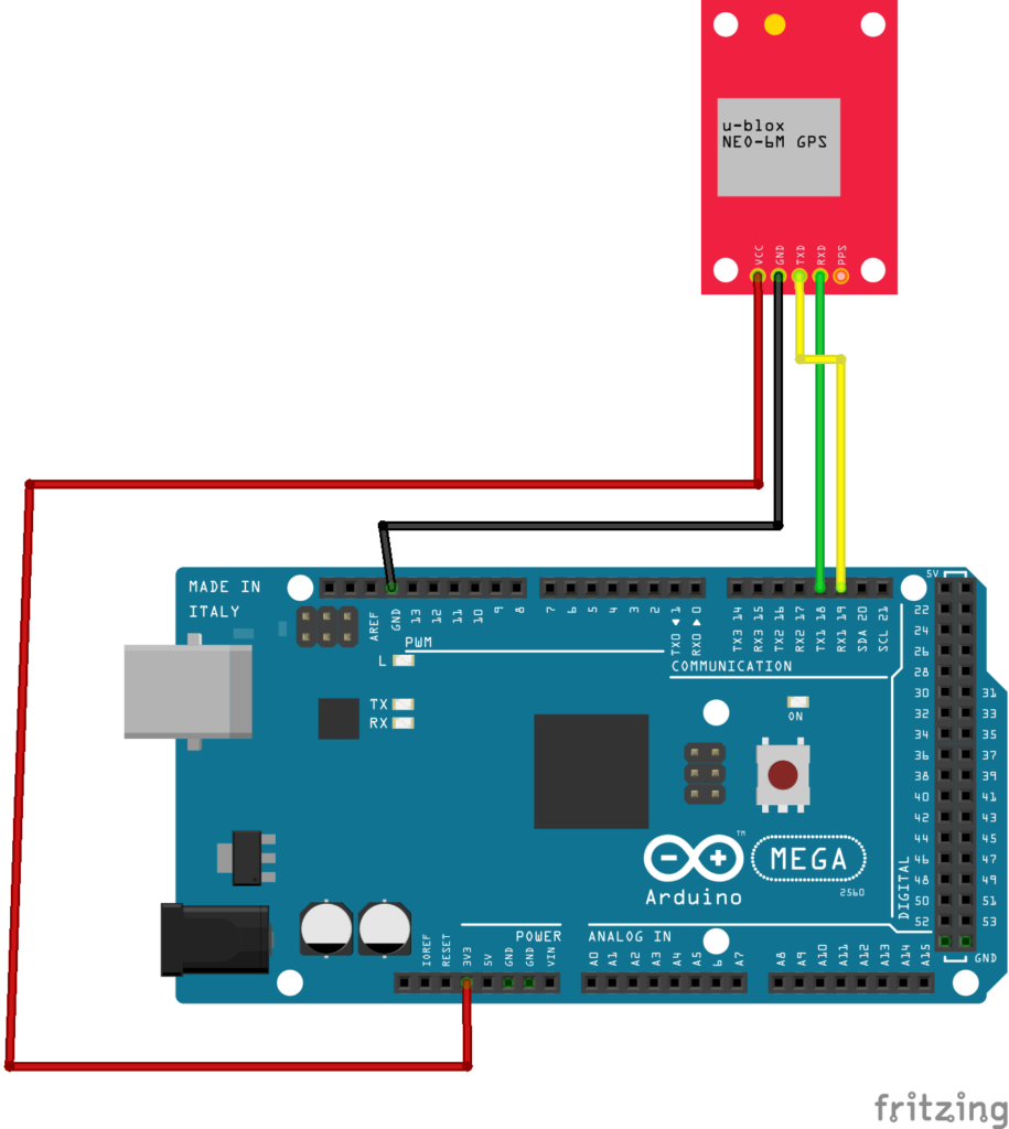
Step 2: Wiring the GPS Module to the ATmega2560
Now that you have selected your GPS module, it’s time to connect it to the ATmega2560. The connections will vary depending on the specific GPS module you have chosen, but in general, you will need to connect the following pins:
- VCC – Connect this pin to the 5V output on the ATmega2560
- GND – Connect this pin to the ground on the ATmega2560
- TX – Connect this pin to the RX pin on the ATmega2560
- RX – Connect this pin to the TX pin on the ATmega2560
Once you have made these connections, you should be all set to start receiving GPS data on your ATmega2560!
Step 3: Writing the Code
Now that your GPS module is connected to the ATmega2560, you’ll need to write some code to communicate with the GPS module and read the incoming data. You can use libraries like TinyGPS or Adafruit_GPS to make this process easier.
Here’s a simple example code snippet to get you started:
#include <SoftwareSerial.h>
SoftwareSerial gpsSerial(10, 11); // RX, TX
void setup() {
Serial.begin(9600);
gpsSerial.begin(9600);
}
void loop() {
while (gpsSerial.available() > 0) {
char c = gpsSerial.read();
Serial.print(c);
}
}
Feel free to customize this code to suit your needs and add any additional features you require.
Step 4: Testing the Setup
Once you have wired up the GPS module and written your code, it’s time to test your setup. Upload the code to your ATmega2560, open the serial monitor in your Arduino IDE, and you should start seeing GPS data being printed out.
Ensure that you are receiving valid GPS coordinates and that the data matches your expected output.
Conclusion
By following these steps, you should now have a GPS module successfully connected to your ATmega2560, allowing you to add location-based capabilities to your projects. Have fun experimenting with GPS and exploring the endless possibilities!
How to Connect a GPS Module to an ATmega2560
If you are looking to add GPS capabilities to your projects using an ATmega2560 microcontroller, you’re in the right place! GPS modules are a great way to add location-based functionality to your projects, whether it’s for tracking, navigation, or simply knowing where you are.
In this guide, we will walk you through the steps on how to connect a GPS module to an ATmega2560 microcontroller, allowing you to easily integrate GPS functionality into your next project.
Step 1: Selecting the Right GPS Module
Before you start connecting anything, you’ll need to choose a GPS module that is compatible with the ATmega2560. There are many GPS modules available in the market, but some popular ones that work well with the ATmega2560 include the NEO-6M and UBlox-6M.
Step 2: Wiring the GPS Module to the ATmega2560
Now that you have selected your GPS module, it’s time to connect it to the ATmega2560. The connections will vary depending on the specific GPS module you have chosen, but in general, you will need to connect the following pins:
- VCC – Connect this pin to the 5V output on the ATmega2560
- GND – Connect this pin to the ground on the ATmega2560
- TX – Connect this pin to the RX pin on the ATmega2560
- RX – Connect this pin to the TX pin on the ATmega2560
Once you have made these connections, you should be all set to start receiving GPS data on your ATmega2560!
Step 3: Writing the Code
Now that your GPS module is connected to the ATmega2560, you’ll need to write some code to communicate with the GPS module and read the incoming data. You can use libraries like TinyGPS or Adafruit_GPS to make this process easier.
Here’s a simple example code snippet to get you started:
#include <SoftwareSerial.h>
SoftwareSerial gpsSerial(10, 11); // RX, TX
void setup() {
Serial.begin(9600);
gpsSerial.begin(9600);
}
void loop() {
while (gpsSerial.available() > 0) {
char c = gpsSerial.read();
Serial.print(c);
}
}
Feel free to customize this code to suit your needs and add any additional features you require.
Step 4: Testing the Setup
Once you have wired up the GPS module and written your code, it’s time to test your setup. Upload the code to your ATmega2560, open the serial monitor in your Arduino IDE, and you should start seeing GPS data being printed out.
Ensure that you are receiving valid GPS coordinates and that the data matches your expected output.
Conclusion
By following these steps, you should now have a GPS module successfully connected to your ATmega2560, allowing you to add location-based capabilities to your projects. Have fun experimenting with GPS and exploring the endless possibilities!