How to Read a Rotary Encoder with Arduino
If you are looking to incorporate rotary encoders into your Arduino projects, you’ve come to the right place. Rotary encoders are electromechanical devices that convert the angular position of a shaft into digital code. They are commonly used in various applications such as robotics, CNC machines, and electronic instruments.
Reading a rotary encoder with Arduino may seem like a daunting task, but with the right guidance, it can be a straightforward process. In this article, we will walk you through the steps to successfully read a rotary encoder with your Arduino board.
Understanding Rotary Encoders
Before we dive into how to read a rotary encoder with Arduino, let’s first understand how rotary encoders work. Rotary encoders can be either incremental or absolute. Incremental rotary encoders generate a series of pulses as the shaft rotates, while absolute rotary encoders output a unique digital code for each position.
Most Arduino projects utilize incremental rotary encoders due to their simplicity and cost-effectiveness. These encoders typically have three pins: one for ground, one for power, and one for the output signal.
The output signal pin of the rotary encoder connects to one of the digital pins on your Arduino board. When the shaft of the encoder is rotated, the output signal pin generates a series of pulses that can be used to determine the direction and distance of rotation.
Reading a Rotary Encoder with Arduino
To read a rotary encoder with Arduino, you will need to write a simple Arduino sketch that monitors the pulses generated by the encoder. Here is a basic outline of the steps involved:
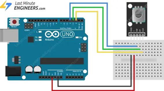
- Connect the ground pin of the rotary encoder to a GND pin on the Arduino board.
- Connect the power pin of the rotary encoder to a 5V pin on the Arduino board.
- Connect the output signal pin of the rotary encoder to a digital pin on the Arduino board, such as pin 2.
- Write a sketch that reads the pulses generated by the encoder and tracks the direction and distance of rotation.
Here is a sample Arduino sketch that demonstrates how to read a rotary encoder:
  // Define the pins
  int encoderPinA = 2;
  int encoderPinB = 3;
  int counter = 0;
  int aState;
  int aLastState;

  void setup() {
    pinMode(encoderPinA, INPUT);
    pinMode(encoderPinB, INPUT);
    Serial.begin(9600);
  }

  void loop() {
    aState = digitalRead(encoderPinA);
    if (aState != aLastState) {
      if (digitalRead(encoderPinB) != aState) {
        counter++;
      } else {
        counter--;
      }
      Serial.println(counter);
    }
    aLastState = aState;
  }
With this sketch, your Arduino will be able to read the pulses generated by the rotary encoder and track the direction and distance of rotation. You can then use this data to control various aspects of your project.
Conclusion
Reading a rotary encoder with Arduino may seem intimidating at first, but with a basic understanding of how these devices work and the right Arduino sketch, you can easily incorporate rotary encoders into your projects. Whether you are building a robotic arm, a 3D printer, or a musical instrument, rotary encoders can add precision and control to your creations.
We hope this article has provided you with the information you need to get started with reading a rotary encoder with Arduino. Experiment with different encoder types and Arduino sketches to discover the full potential of these versatile devices. Happy coding!
How to Read a Rotary Encoder with Arduino
If you are looking to incorporate rotary encoders into your Arduino projects, you’ve come to the right place. Rotary encoders are electromechanical devices that convert the angular position of a shaft into digital code. They are commonly used in various applications such as robotics, CNC machines, and electronic instruments.
Reading a rotary encoder with Arduino may seem like a daunting task, but with the right guidance, it can be a straightforward process. In this article, we will walk you through the steps to successfully read a rotary encoder with your Arduino board.
Understanding Rotary Encoders
Before we dive into how to read a rotary encoder with Arduino, let’s first understand how rotary encoders work. Rotary encoders can be either incremental or absolute. Incremental rotary encoders generate a series of pulses as the shaft rotates, while absolute rotary encoders output a unique digital code for each position.
Most Arduino projects utilize incremental rotary encoders due to their simplicity and cost-effectiveness. These encoders typically have three pins: one for ground, one for power, and one for the output signal.
The output signal pin of the rotary encoder connects to one of the digital pins on your Arduino board. When the shaft of the encoder is rotated, the output signal pin generates a series of pulses that can be used to determine the direction and distance of rotation.
Reading a Rotary Encoder with Arduino
To read a rotary encoder with Arduino, you will need to write a simple Arduino sketch that monitors the pulses generated by the encoder. Here is a basic outline of the steps involved:
- Connect the ground pin of the rotary encoder to a GND pin on the Arduino board.
- Connect the power pin of the rotary encoder to a 5V pin on the Arduino board.
- Connect the output signal pin of the rotary encoder to a digital pin on the Arduino board, such as pin 2.
- Write a sketch that reads the pulses generated by the encoder and tracks the direction and distance of rotation.
Here is a sample Arduino sketch that demonstrates how to read a rotary encoder:
  // Define the pins
  int encoderPinA = 2;
  int encoderPinB = 3;
  int counter = 0;
  int aState;
  int aLastState;

  void setup() {
    pinMode(encoderPinA, INPUT);
    pinMode(encoderPinB, INPUT);
    Serial.begin(9600);
  }

  void loop() {
    aState = digitalRead(encoderPinA);
    if (aState != aLastState) {
      if (digitalRead(encoderPinB) != aState) {
        counter++;
      } else {
        counter--;
      }
      Serial.println(counter);
    }
    aLastState = aState;
  }
With this sketch, your Arduino will be able to read the pulses generated by the rotary encoder and track the direction and distance of rotation. You can then use this data to control various aspects of your project.
Conclusion
Reading a rotary encoder with Arduino may seem intimidating at first, but with a basic understanding of how these devices work and the right Arduino sketch, you can easily incorporate rotary encoders into your projects. Whether you are building a robotic arm, a 3D printer, or a musical instrument, rotary encoders can add precision and control to your creations.
We hope this article has provided you with the information you need to get started with reading a rotary encoder with Arduino. Experiment with different encoder types and Arduino sketches to discover the full potential of these versatile devices. Happy coding!