How to Use a KA3525 PWM Controller
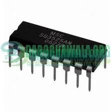
If you’re looking to control the pulse width modulation (PWM) of your circuit, a KA3525 PWM controller is a great option. This device is commonly used in power supplies and voltage regulators to control the output voltage through PWM. In this article, we’ll guide you through the steps on how to use a KA3525 PWM controller effectively.
Step 1: Understand the Basics
Before using the KA3525 PWM controller, it’s important to understand the basic functionality and components of the device. The KA3525 is a pulse width modulation (PWM) controller that operates at a fixed frequency. It includes an oscillator, voltage reference, error amplifier, comparator, pulse-steering flip-flop, and an output control circuit.
The key components of the KA3525 include the oscillator, which generates the fixed frequency, and the error amplifier, which compares the feedback voltage with the reference voltage. The comparator then outputs a signal to the pulse-steering flip-flop, which adjusts the duty cycle of the PWM signal. The final output control circuit regulates the output voltage based on the duty cycle of the PWM signal.
Step 2: Connect the Components
Once you have a good grasp of the basic components of the KA3525 PWM controller, it’s time to connect the components to set up your circuit. Begin by connecting the power supply and ground pins of the KA3525 to the appropriate power source. Next, connect the feedback pin to the output voltage of your circuit.
You’ll also need to connect the error amplifier, oscillator, comparator, and output control circuit according to your specific circuit requirements. It’s important to follow the datasheet of the KA3525 for the correct pin configurations and connections to ensure proper functionality.
Step 3: Configure the Settings
After connecting the components, it’s time to configure the settings of the KA3525 PWM controller. Start by adjusting the reference voltage of the error amplifier to set the desired output voltage. You can do this by adjusting the resistors and capacitors connected to the error amplifier pin.
Next, adjust the frequency of the oscillator to achieve the desired switching frequency. You can do this by changing the resistor and capacitor values connected to the oscillator pin. Finally, adjust the duty cycle of the PWM signal by manipulating the pulse-steering flip-flop.
Step 4: Test and Troubleshoot
Once you have connected the components and configured the settings, it’s time to test the functionality of the KA3525 PWM controller. Apply power to your circuit and observe the output voltage. If the output voltage is not stable or at the desired level, you may need to troubleshoot the circuit.
Check the connections, component placement, and settings of the KA3525 PWM controller to identify any potential issues. Make adjustments as needed and retest the circuit until you achieve the desired output voltage stability.
By following these steps, you’ll be able to effectively use a KA3525 PWM controller in your circuit. Remember to refer to the datasheet of the KA3525 for detailed information on the device specifications and operating conditions. With practice and experimentation, you’ll become proficient in using the KA3525 PWM controller to control the PWM of your circuits.


