How to Use an MCP4725 DAC Module
Are you looking to add analog output capabilities to your microcontroller projects? The MCP4725 DAC (Digital-to-Analog Converter) module is a great tool for converting digital values to analog signals. In this guide, we will walk you through the process of using the MCP4725 DAC module with an Arduino or Raspberry Pi.
Before we dive into the tutorial, let’s understand what a DAC is and how it can be useful in your projects. A DAC takes a digital input and converts it into a corresponding analog output voltage. This is particularly useful for controlling things like motor speeds, LED brightness, or generating audio signals.
Materials Required
- MCP4725 DAC module
- Arduino or Raspberry Pi
- Jumper wires
- Breadboard
- Power supply
Connecting the MCP4725 DAC Module
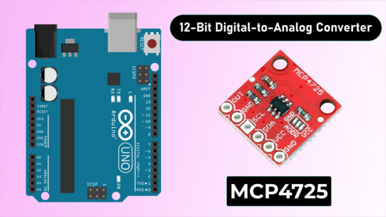
First, connect the MCP4725 DAC module to your microcontroller using jumper wires. The MCP4725 module usually has four pins: VCC (power), GND (ground), SDA (data), and SCL (clock). Connect the VCC and GND pins to the 3.3V or 5V pins on your microcontroller, and connect the SDA and SCL pins to the respective data and clock pins on the microcontroller.
If you are using an Arduino, you can use the Wire library to communicate with the MCP4725 DAC module. For Raspberry Pi, you can use the smbus library. Make sure to install the necessary libraries before proceeding.
Programming the MCP4725 DAC Module
Once you have connected the MCP4725 DAC module to your microcontroller, it’s time to write some code. The MCP4725 module uses I2C communication, so you will need to send commands to set the output voltage. You can set the output voltage by writing the desired value to the DAC’s internal register.
Here is a simple example code for Arduino:
#include
#define MCP4725_ADDR 0x62
void setup() {
  Wire.begin();
}
void loop() {
  // Set output voltage to 2.5V
  Wire.beginTransmission(MCP4725_ADDR);
  Wire.write(64); // CMD: DAC output and GAIN configuration
  Wire.write(63); // 2.5V = 2048 (Vout = Vref * value / 4096)
  Wire.endTransmission();
  delay(1000);
}
For Raspberry Pi, the code will be a bit different but will follow a similar structure. Make sure to consult the MCP4725 DAC module’s datasheet for more details on the communication protocol and commands.
Testing the MCP4725 DAC Module
After writing the code and uploading it to your microcontroller, you can now test the MCP4725 DAC module. Connect a multimeter to the output pin of the module to measure the analog voltage. By changing the value in the code, you can adjust the output voltage accordingly.
Experiment with different values and see how the output voltage changes. You can use this module for various applications, such as creating audio waves, controlling LED brightness, or interfacing with analog sensors.
That’s it! You have now learned how to use the MCP4725 DAC module with your microcontroller. Get creative and integrate it into your projects to add analog output capabilities.
Was this helpful?
0 / 0