How to Connect a 4N35 Optocoupler
Optocouplers, also known as optoisolators, are electronic components used to transfer electrical signals between two isolated circuits by using light. The 4N35 is a popular optocoupler widely used in electronic circuits for interfacing low voltage and high voltage devices. In this article, we will guide you on how to connect a 4N35 optocoupler effectively.
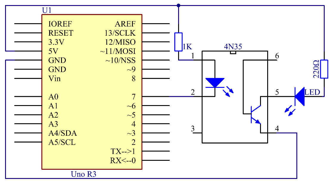
When connecting a 4N35 optocoupler, it is essential to pay attention to the pinout and datasheet of the component. The 4N35 optocoupler consists of an infrared emitting diode and a phototransistor connected in a single package. Here is a step-by-step guide on how to connect a 4N35 optocoupler:
Step 1: Identify the Pins
Before connecting the 4N35 optocoupler, identify the pins of the component. The 4N35 optocoupler typically has 6 pins: Anode, Cathode, Collector, Emitter, and two base pins. Refer to the datasheet of the 4N35 optocoupler to determine the pin configuration accurately.
Step 2: Connect the Anode and Cathode
Connect the Anode (A) and Cathode (K) pins of the 4N35 optocoupler to the power supply to ensure proper operation. The Anode is typically connected to the positive terminal of the power supply, while the Cathode is connected to the negative terminal.
Step 3: Connect the Collector and Emitter
Connect the Collector (C) and Emitter (E) pins of the 4N35 optocoupler to the input and output circuits, respectively. The Collector pin receives the input signal, while the Emitter pin transfers the output signal. Ensure proper connections to maintain isolation between the circuits.
Step 4: Connect the Base Pins
The 4N35 optocoupler may have two Base pins, Base 1 and Base 2, which are used to control the operation of the phototransistor. Connect the Base pins according to the requirements of your circuit design to achieve the desired functionality.
Step 5: Test the Connection
After connecting the 4N35 optocoupler following the steps mentioned above, it is crucial to test the connection to ensure proper functionality. Apply input signals to the Collector pin and observe the output signals at the Emitter pin. Verify that the signals are properly isolated and transferred between the circuits.
Conclusion
Connecting a 4N35 optocoupler is a crucial step in many electronic circuits requiring isolation between low and high voltage devices. By following the steps outlined in this article and referring to the datasheet of the component, you can effectively connect a 4N35 optocoupler for your circuit applications. Remember to test the connection to ensure proper functionality and isolation between the circuits.
Was this helpful?
0 / 0