How to Wire a ULN2003 Relay Driver
Are you looking to learn how to wire a ULN2003 relay driver for your upcoming project? Look no further, as we walk you through the process step by step in this comprehensive guide.
What is a ULN2003 Relay Driver?
Before we dive into the wiring process, let’s first understand what a ULN2003 relay driver is. The ULN2003 is a high-voltage, high-current Darlington transistor array. It is commonly used to drive relays, stepper motors, and other high-current peripheral devices in electronic circuits.
Materials Needed
- ULN2003 relay driver
- Relay
- Microcontroller or Arduino
- Jumper wires
- Power source
Wiring Instructions
Follow these steps to wire a ULN2003 relay driver:
Step 1: Connect Power Supply
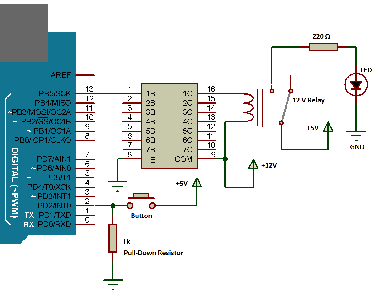
Connect the positive terminal of your power source to the VCC pin on the ULN2003 board and the negative terminal to the GND pin.
Step 2: Connect the Relay
Connect the input pins of the relay to the output pins of the ULN2003 driver. Make sure to check the datasheet of your specific relay for the correct pin configuration.
Step 3: Connect to Microcontroller
Connect the IN1, IN2, IN3, and IN4 pins on the ULN2003 board to the digital output pins on your microcontroller or Arduino board.
Testing the Circuit
Before powering up your circuit, double-check all connections to ensure everything is properly wired. Once you are confident in your wiring, apply power to the circuit and test the relay operation using your microcontroller.
Conclusion
Wiring a ULN2003 relay driver is a straightforward process that can add functionality to your electronic projects. By following the steps outlined in this guide, you’ll be able to control high-current devices with ease. Good luck with your project!
Was this helpful?
0 / 0