Best Way to Make a Digital Voltmeter Circuit
Are you looking to make your own digital voltmeter circuit but not sure where to start? In this article, we will guide you through the best way to create a digital voltmeter circuit from scratch. Whether you are a beginner or an experienced electronics hobbyist, this step-by-step guide will help you understand the process and build your own digital voltmeter circuit with ease.
Understanding the Basics
Before we dive into building the digital voltmeter circuit, it is important to understand the basic components and principles involved. A digital voltmeter is a measuring instrument used to measure voltage levels in an electronic circuit. It displays the voltage reading in numerical form, making it easier for users to read and interpret the results.
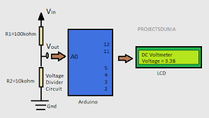
The key components of a digital voltmeter circuit include an analog-to-digital converter (ADC), a microcontroller, a display unit (such as an LCD or LED display), and voltage dividers. The ADC is responsible for converting the analog voltage signal into a digital format that can be read by the microcontroller. The microcontroller processes the digital data and sends it to the display unit for visualization.
Gathering the Components
Now that you have a basic understanding of the digital voltmeter circuit, it’s time to gather the necessary components for your project. Here is a list of components that you will need:
- Microcontroller (Arduino or PIC)
- Analog-to-Digital Converter (ADC)
- LCD or LED Display
- Voltage Dividers
- Resistors
- Breadboard
- Jumper Wires
- Power Supply
You can easily find these components at your local electronics store or online retailer. Make sure to double-check the specifications of each component to ensure compatibility with your circuit design.
Building the Circuit
Once you have all the components in hand, it’s time to start building the digital voltmeter circuit. Follow these steps to assemble the circuit on a breadboard:
- Connect the voltage dividers to the input pins of the ADC
- Connect the output pins of the ADC to the microcontroller
- Connect the microcontroller to the display unit
- Place the resistors in the circuit to ensure proper voltage division
- Connect the power supply to the circuit
Once you have assembled the circuit on the breadboard, double-check all the connections to ensure they are secure and properly connected. Now, power up the circuit and test the digital voltmeter with different voltage inputs to verify its accuracy and performance.
Programming the Microcontroller
After building the circuit, you will need to program the microcontroller to read the ADC data and display the voltage readings on the display unit. If you are using an Arduino microcontroller, you can use the Arduino IDE to write and upload the code to the board.
Here is a simple example code snippet to get you started:
void setup() {
  // Initialize the ADC and display unit
}

void loop() {
  // Read the voltage from the ADC
  // Display the voltage reading on the display unit
}
Feel free to customize the code based on your circuit design and requirements. Once you have uploaded the code to the microcontroller, power up the circuit and test the digital voltmeter to ensure it is working as expected.
Conclusion
Congratulations! You have successfully built your own digital voltmeter circuit from scratch. By following the steps outlined in this article, you now have a better understanding of how digital voltmeter circuits work and how to create one yourself. Experiment with different components and circuit designs to enhance your skills and knowledge in electronics.
If you have any questions or need further assistance, feel free to reach out to the online community or electronics forums for help. Enjoy the process of building and experimenting with digital voltmeter circuits, and happy tinkering!
Best Way to Make a Digital Voltmeter Circuit
Are you looking to make your own digital voltmeter circuit but not sure where to start? In this article, we will guide you through the best way to create a digital voltmeter circuit from scratch. Whether you are a beginner or an experienced electronics hobbyist, this step-by-step guide will help you understand the process and build your own digital voltmeter circuit with ease.
Understanding the Basics
Before we dive into building the digital voltmeter circuit, it is important to understand the basic components and principles involved. A digital voltmeter is a measuring instrument used to measure voltage levels in an electronic circuit. It displays the voltage reading in numerical form, making it easier for users to read and interpret the results.
The key components of a digital voltmeter circuit include an analog-to-digital converter (ADC), a microcontroller, a display unit (such as an LCD or LED display), and voltage dividers. The ADC is responsible for converting the analog voltage signal into a digital format that can be read by the microcontroller. The microcontroller processes the digital data and sends it to the display unit for visualization.
Gathering the Components
Now that you have a basic understanding of the digital voltmeter circuit, it’s time to gather the necessary components for your project. Here is a list of components that you will need:
- Microcontroller (Arduino or PIC)
- Analog-to-Digital Converter (ADC)
- LCD or LED Display
- Voltage Dividers
- Resistors
- Breadboard
- Jumper Wires
- Power Supply
You can easily find these components at your local electronics store or online retailer. Make sure to double-check the specifications of each component to ensure compatibility with your circuit design.
Building the Circuit
Once you have all the components in hand, it’s time to start building the digital voltmeter circuit. Follow these steps to assemble the circuit on a breadboard:
- Connect the voltage dividers to the input pins of the ADC
- Connect the output pins of the ADC to the microcontroller
- Connect the microcontroller to the display unit
- Place the resistors in the circuit to ensure proper voltage division
- Connect the power supply to the circuit
Once you have assembled the circuit on the breadboard, double-check all the connections to ensure they are secure and properly connected. Now, power up the circuit and test the digital voltmeter with different voltage inputs to verify its accuracy and performance.
Programming the Microcontroller
After building the circuit, you will need to program the microcontroller to read the ADC data and display the voltage readings on the display unit. If you are using an Arduino microcontroller, you can use the Arduino IDE to write and upload the code to the board.
Here is a simple example code snippet to get you started:
void setup() {
  // Initialize the ADC and display unit
}

void loop() {
  // Read the voltage from the ADC
  // Display the voltage reading on the display unit
}
Feel free to customize the code based on your circuit design and requirements. Once you have uploaded the code to the microcontroller, power up the circuit and test the digital voltmeter to ensure it is working as expected.
Conclusion
Congratulations! You have successfully built your own digital voltmeter circuit from scratch. By following the steps outlined in this article, you now have a better understanding of how digital voltmeter circuits work and how to create one yourself. Experiment with different components and circuit designs to enhance your skills and knowledge in electronics.
If you have any questions or need further assistance, feel free to reach out to the online community or electronics forums for help. Enjoy the process of building and experimenting with digital voltmeter circuits, and happy tinkering!