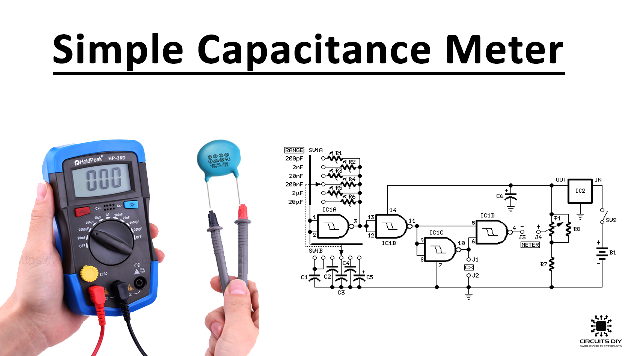
How to Make a Simple Capacitance Meter
Capacitance is an important concept in electronics, as it determines the ability of a component to store an electrical charge. Having a capacitance meter can be very useful for both hobbyists and professionals in the field. In this article, we will guide you on how to make a simple capacitance meter using basic electronic components.
Materials Needed
- Breadboard
- Jumper wires
- 10 kΩ resistor
- 1 μF capacitor
- 555 timer IC
- LED
- 9V battery
Step-by-Step Instructions
Follow these steps to make your own capacitance meter:
Step 1: Build the Circuit
Start by placing the 555 timer IC on the breadboard. Connect pin 3 (output) to pin 2 (trigger) and pin 6 (threshold) using jumper wires. Connect pin 5 (control) to ground and pin 4 (reset) to the positive rail (+V). Connect the LED to pin 3 through a 10 kΩ resistor.
Step 2: Add the Capacitor
Connect the 1 μF capacitor between pin 2 (trigger) and ground. This capacitor will be charged and discharged by the 555 timer, and the LED will indicate the timing of the charging process.
Step 3: Test the Meter
Apply a 9V power supply to the circuit and observe the LED. The LED will blink at a frequency determined by the capacitance of the capacitor. You can use this blinking frequency to calculate the capacitance value using a simple formula.
Conclusion
Congratulations! You have successfully built a simple capacitance meter using basic electronic components. Experiment with different capacitors and observe how the LED blink frequency changes. This project is a great way to learn more about capacitance and electronic circuits.
Was this helpful?
0 / 0