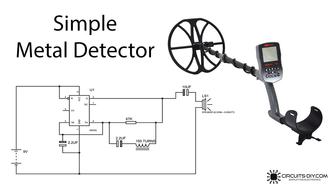
How to Design a Basic Metal Detector Circuit
Ever wanted to build your own metal detector? Whether you’re a DIY enthusiast or just curious about electronics, designing a basic metal detector circuit can be a fun and rewarding project. In this article, we’ll walk you through the process of creating a simple metal detector circuit using common electronic components. Let’s get started!
Materials Needed
- 555 Timer IC
- Coil of wire (inductor)
- Capacitor
- Resistors
- Breadboard
- Battery
- LED
- Switch
- Speaker
Step 1: Build the Oscillator Circuit
The first step in designing a metal detector circuit is to build the oscillator circuit. This circuit generates an alternating current (AC) signal that is sent through the coil of wire. The 555 Timer IC is commonly used to create the oscillator circuit.
Step 2: Add the Inductor Coil
Next, connect the inductor coil to the oscillator circuit. The inductor coil acts as the metal detector’s sensor, detecting changes in the magnetic field when a metal object is nearby.
Step 3: Connect the LED and Speaker
To indicate when a metal object is detected, connect an LED and a speaker to the circuit. When the metal detector senses a metal object, the LED will light up and the speaker will emit a sound.
Step 4: Test Your Metal Detector
Once you’ve completed building the metal detector circuit, it’s time to test it out. Place a metal object near the coil and observe the LED lighting up and the speaker making a sound. Congratulations, you’ve successfully designed a basic metal detector circuit!
Conclusion
Designing a basic metal detector circuit is a fun and educational project that can be completed with just a few electronic components. By following the steps outlined in this article, you can create your own metal detector and learn more about the principles of electronics along the way. Happy building!
Was this helpful?
0 / 0