How to Build a Homemade Function Generator
Are you interested in electronics and looking to build your own function generator? A function generator is a versatile tool that generates various waveforms, such as sine, square, triangle, and sawtooth waves. While commercial function generators can be expensive, you can easily build your own homemade function generator using basic electronic components.
In this article, we will guide you through the process of building a simple function generator that you can use for various electronic projects.
Components You Will Need
Before we begin, here are the components you will need to build your homemade function generator:
- 555 Timer IC
- Capacitors (1μF, 10μF)
- Resistors (1kΩ, 10kΩ, 100kΩ)
- Potentiometer (10kΩ)
- Transistor (BC547)
- LED
- Breadboard
- Jumper wires
- Power supply (5V)
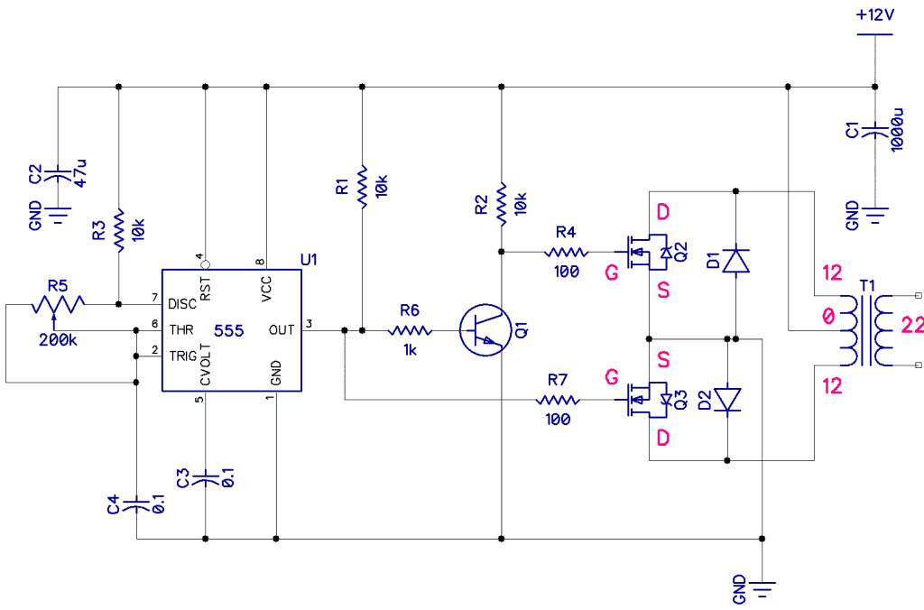
Circuit Diagram
First, let’s take a look at the circuit diagram of our homemade function generator:

Building the Function Generator
Now, let’s move on to building the function generator. Follow these steps:
- Place the 555 Timer IC on the breadboard.
- Connect pin 1 (GND) to the ground rail of the breadboard.
- Connect pin 4 (Reset) to pin 8 (Vcc) using a 10kΩ resistor.
- Connect pin 8 (Vcc) to the positive rail of the breadboard.
- Connect pin 5 (Control Voltage) to pin 7 (Discharge) using a 0.01μF capacitor.
- Connect pin 2 (Trigger) to pin 6 (Threshold) using a 0.01μF capacitor.
- Connect pin 6 (Threshold) to pin 7 (Discharge) using a 1kΩ resistor.
- Connect pin 2 (Trigger) to pin 7 (Discharge) using a 1kΩ resistor.
- Connect pin 7 (Discharge) to pin 6 (Threshold) using a 10nF capacitor.
- Connect pin 3 (Output) to the base of the BC547 transistor through a 1kΩ resistor.
- Connect the emitter of the transistor to the ground rail of the breadboard.
- Connect the collector of the transistor to the positive rail of the breadboard through a 100Ω resistor.
- Connect an LED in series with a 470Ω resistor across the collector and the ground rail of the breadboard.
- Connect a potentiometer between pin 5 (Control Voltage) and the positive rail of the breadboard.
- Connect pin 8 (Vcc) of the potentiometer to the positive rail of the breadboard.
Testing the Function Generator
After building the function generator, it’s time to test it. Connect a power supply of 5V to the circuit and adjust the potentiometer to vary the output frequency. You should see the LED blink at different rates, indicating that the function generator is working.
Conclusion
Congratulations! You have successfully built your own homemade function generator. Experiment with different waveforms and frequencies to explore the capabilities of your new tool. Have fun with your electronic projects!
How to Build a Homemade Function Generator
Are you interested in electronics and looking to build your own function generator? A function generator is a versatile tool that generates various waveforms, such as sine, square, triangle, and sawtooth waves. While commercial function generators can be expensive, you can easily build your own homemade function generator using basic electronic components.
In this article, we will guide you through the process of building a simple function generator that you can use for various electronic projects.
Components You Will Need
Before we begin, here are the components you will need to build your homemade function generator:
- 555 Timer IC
- Capacitors (1μF, 10μF)
- Resistors (1kΩ, 10kΩ, 100kΩ)
- Potentiometer (10kΩ)
- Transistor (BC547)
- LED
- Breadboard
- Jumper wires
- Power supply (5V)
Circuit Diagram
First, let’s take a look at the circuit diagram of our homemade function generator:
Building the Function Generator
Now, let’s move on to building the function generator. Follow these steps:
- Place the 555 Timer IC on the breadboard.
- Connect pin 1 (GND) to the ground rail of the breadboard.
- Connect pin 4 (Reset) to pin 8 (Vcc) using a 10kΩ resistor.
- Connect pin 8 (Vcc) to the positive rail of the breadboard.
- Connect pin 5 (Control Voltage) to pin 7 (Discharge) using a 0.01μF capacitor.
- Connect pin 2 (Trigger) to pin 6 (Threshold) using a 0.01μF capacitor.
- Connect pin 6 (Threshold) to pin 7 (Discharge) using a 1kΩ resistor.
- Connect pin 2 (Trigger) to pin 7 (Discharge) using a 1kΩ resistor.
- Connect pin 7 (Discharge) to pin 6 (Threshold) using a 10nF capacitor.
- Connect pin 3 (Output) to the base of the BC547 transistor through a 1kΩ resistor.
- Connect the emitter of the transistor to the ground rail of the breadboard.
- Connect the collector of the transistor to the positive rail of the breadboard through a 100Ω resistor.
- Connect an LED in series with a 470Ω resistor across the collector and the ground rail of the breadboard.
- Connect a potentiometer between pin 5 (Control Voltage) and the positive rail of the breadboard.
- Connect pin 8 (Vcc) of the potentiometer to the positive rail of the breadboard.
Testing the Function Generator
After building the function generator, it’s time to test it. Connect a power supply of 5V to the circuit and adjust the potentiometer to vary the output frequency. You should see the LED blink at different rates, indicating that the function generator is working.
Conclusion
Congratulations! You have successfully built your own homemade function generator. Experiment with different waveforms and frequencies to explore the capabilities of your new tool. Have fun with your electronic projects!