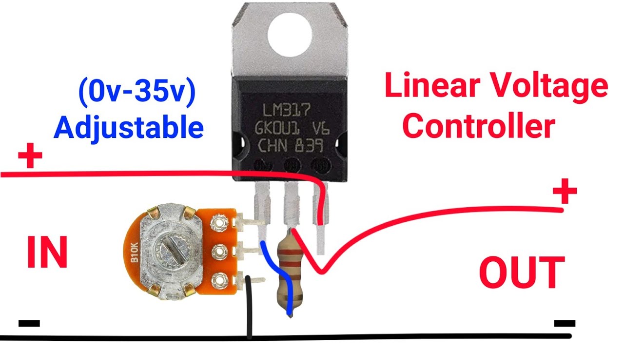
How to Make a Voltage Regulator Circuit
Are you tired of dealing with fluctuating voltage levels in your electronics projects? A voltage regulator circuit can help you maintain a stable voltage output, regardless of input fluctuations. In this article, we’ll guide you through the process of building a simple voltage regulator circuit from scratch. Let’s get started!
Materials Needed
- Breadboard
- LM7805 Voltage Regulator IC
- 100uF Capacitor
- 1uF Capacitor
- 0.1uF Capacitor
- 10uF Capacitor
- 1k Ohm Resistor
- LED
Step 1: Connect the LM7805 IC
Place the LM7805 voltage regulator IC on the breadboard, ensuring that the pins are inserted in the correct slots. The LM7805 IC will help regulate the output voltage to a stable 5V.
Step 2: Connect the Capacitors
Connect the 100uF capacitor between the input voltage pin (pin 1) and the ground pin (pin 2) of the LM7805 IC. This capacitor will help smooth out any input voltage fluctuations. Connect the 1uF capacitor between the output voltage pin (pin 3) and the ground pin (pin 2) to stabilize the output voltage.
Step 3: Add the Resistor and LED
Connect the 1k ohm resistor between the output voltage pin (pin 3) of the LM7805 IC and the anode of the LED. Connect the cathode of the LED to the ground pin (pin 2) of the LM7805 IC. The LED will indicate when the circuit is powered.
Step 4: Test the Circuit
Apply an input voltage to the LM7805 IC and use a multimeter to measure the output voltage. The output voltage should be a stable 5V. If the LED lights up, it indicates that the circuit is functioning correctly.
Congratulations! You’ve successfully built a voltage regulator circuit. Feel free to experiment with different components and configurations to customize the circuit to suit your needs.
Remember to always double-check your connections and follow proper safety precautions when working with electronics. Have fun tinkering!
Was this helpful?
0 / 0