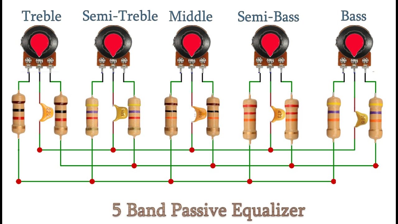
How to Make a DIY Audio Equalizer Circuit
If you enjoy tinkering with electronics and want to customize the audio output of your sound system, building your own DIY audio equalizer circuit can be a rewarding project. An audio equalizer allows you to adjust the volume levels of different frequency bands, giving you more control over the sound quality. In this tutorial, we will guide you through the process of building a simple yet effective audio equalizer circuit.
Materials Needed:
- Breadboard
- Op-Amp IC (LM741 or LM358)
- Resistors (Various Values)
- Capacitors (Various Values)
- Potentiometers (Various Values)
- Audio input/output connectors
- Jumper wires
- Power supply (5-12V)
Step 1: Circuit Design
Start by designing the circuit layout on a piece of paper or using a circuit design software. The basic audio equalizer circuit consists of multiple bandpass filters in parallel, each catering to a specific frequency range. The input signal is divided into these frequency bands, and each band is then individually amplified or attenuated using potentiometers.
For this tutorial, we will build a 3-band audio equalizer with controls for the bass, midrange, and treble frequencies. You can adjust the values of the resistors and capacitors to customize the frequency ranges according to your preferences.
Step 2: Build the Circuit
1. Start by placing the Op-Amp IC on the breadboard. Connect the power supply to the IC, ensuring that the correct polarity is maintained.
2. Connect the audio input to the non-inverting terminal (+) of the Op-Amp IC.
3. Connect the output of each bandpass filter to a separate potentiometer. The potentiometers will act as the volume controls for each frequency band.
4. Connect the output of the potentiometers to the audio output connector.
5. Power up the circuit and test the audio equalizer by playing some music and adjusting the potentiometers to enhance the different frequency bands.
Step 3: Troubleshooting
If you encounter any issues with the circuit, double-check the connections and component values. Make sure that the Op-Amp IC is receiving the correct voltage and that the potentiometers are functioning properly. You can also use an oscilloscope or a multimeter to debug any signal processing errors.
Step 4: Customize and Experiment
Once you have built the basic audio equalizer circuit, you can experiment with different component values and configurations to achieve your desired sound profile. You can also add additional frequency bands or features such as a graphic display for visual feedback.
Remember to have fun and be creative with your DIY audio equalizer project. Building your own circuit allows you to customize the audio output to suit your preferences and learn more about electronics in the process. Happy tinkering!
Was this helpful?
0 / 0