How to Build a Simple 555 Timer Circuit
Welcome to our step-by-step guide on how to build a simple 555 timer circuit. The 555 timer is a versatile integrated circuit that can be used for a variety of timer, pulse, and oscillator applications. Whether you’re a beginner or an experienced electronics enthusiast, this circuit is a great starting point for learning and experimenting with electronics.
Before we begin, let’s briefly discuss what a 555 timer IC is and how it works. The 555 timer is a popular IC that can be used to generate accurate time delays or oscillations. It has three operating modes: monostable, astable, and bistable. In this guide, we will focus on building an astable 555 timer circuit, which will generate a continuous square wave signal.
Components Needed:
- 555 Timer IC
- Two 10kΩ Resistors
- One 100kΩ Resistor
- One 10nF Capacitor
- One 100nF Capacitor
- Breadboard
- Jumper Wires
- Battery + Connector
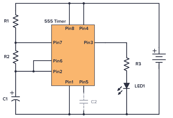
Circuit Diagram:

Step-by-Step Instructions:
1. Insert the 555 timer IC into the breadboard, ensuring that the notch on the IC aligns with the notch on the breadboard.
2. Connect pin 1 of the 555 timer IC to ground (GND).
3. Connect pin 4 of the 555 timer IC to the positive supply voltage (+V).
4. Connect pins 2 and 6 of the 555 timer IC to each other using a 10kΩ resistor.
5. Connect pin 6 of the 555 timer IC to pin 7 through a 100kΩ resistor.
6. Connect pin 2 of the 555 timer IC to pin 6 through a 10nF capacitor.
7. Connect pin 3 of the 555 timer IC to pin 6.
8. Connect the output pin (pin 3) of the 555 timer IC to an LED through a current-limiting resistor.
9. Connect the positive terminal of the battery to pin 8 of the 555 timer IC and the negative terminal to ground (GND).
10. Power up the circuit and you should see the LED blinking, indicating that the 555 timer circuit is working properly.
Final Thoughts:
Congratulations! You’ve successfully built a simple 555 timer circuit. This circuit can be a fun way to learn about electronics and experiment with different timing applications. Feel free to modify the values of the resistors and capacitors to change the frequency and duty cycle of the square wave signal. Have fun exploring and creating with your new 555 timer circuit!
Was this helpful?
0 / 0