How to Find a Ground Connection on a PCB
When working with printed circuit boards (PCBs), one of the most critical aspects is ensuring a proper ground connection. Grounding is essential for the functionality and safety of electronic devices, as it provides a reference point for all electrical circuits. In this article, we will discuss some tips and techniques on how to find a ground connection on a PCB.
Understanding Grounding in a PCB
Grounding on a PCB serves multiple purposes. It helps to stabilize the voltage levels, reduce electromagnetic interference, and improve the overall performance of the circuit. Most PCBs have multiple ground connections, including power ground, signal ground, and chassis ground. It is crucial to identify and connect these grounds correctly to ensure the proper operation of the device.
Identifying Ground Connections
There are several methods to identify ground connections on a PCB:
- Check the PCB Layout: The first step is to examine the PCB layout. Ground connections are typically indicated by symbols such as a triangle pointing downwards or the letters “GND.” Look for these markings to locate the ground connections.
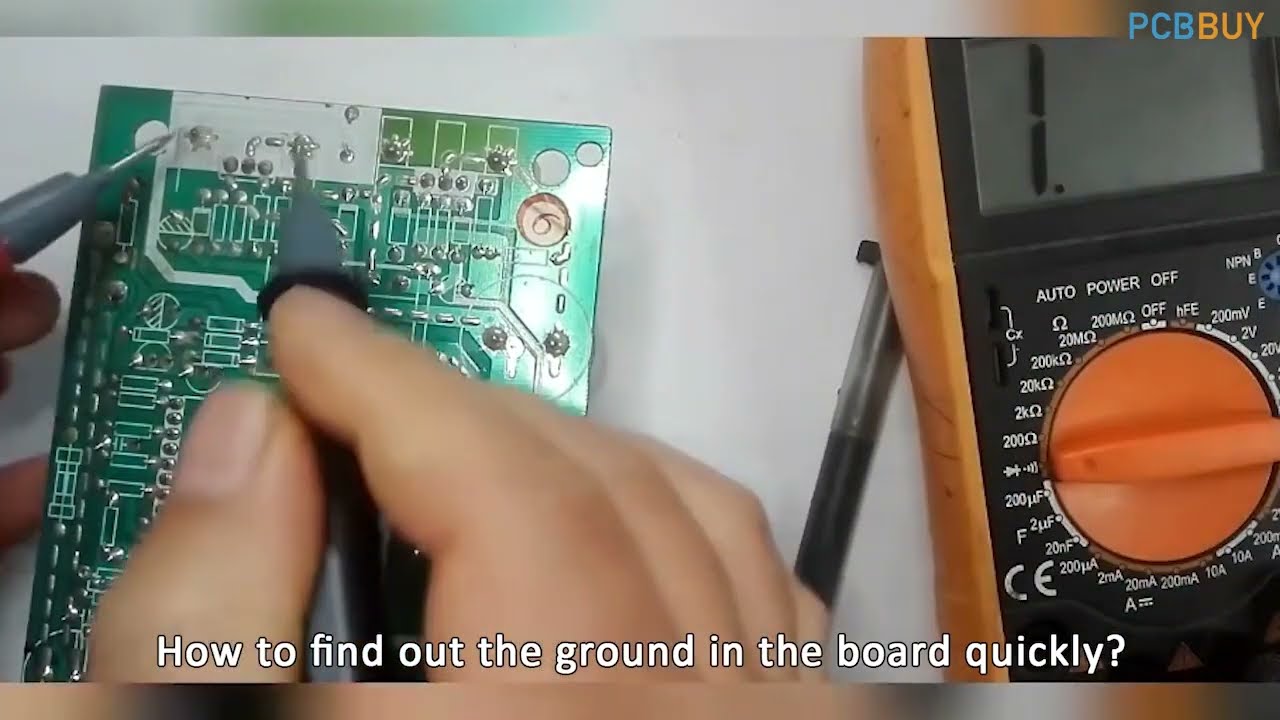
- Use a Multimeter: Another method is to use a multimeter to measure the continuity between different points on the PCB. Connect one probe to a known ground point, such as the negative terminal of a battery, and touch the other probe to various points on the PCB. If you hear a beep or see a low resistance reading, it indicates a ground connection.
- Follow Traces: Trace the copper lines on the PCB to identify the paths that lead to ground connections. Look for large copper areas or traces that connect to components known to require a ground connection, such as voltage regulators or capacitors.
Verifying Ground Connections
After identifying potential ground connections, it is essential to verify their functionality. One way to do this is to perform a continuity test using a multimeter. Check the resistance between the ground connections and the actual ground point, such as the metal chassis of the device. A low resistance reading indicates a proper ground connection.
It is also recommended to perform a visual inspection of the ground connections, looking for any signs of damage or poor soldering. Ensure that the ground connections are secure and free from any foreign objects that may cause a short circuit.
Conclusion
Proper grounding is essential for the reliable operation of electronic devices. By following the tips and techniques outlined in this article, you can effectively locate and verify ground connections on a PCB. Remember to always double-check your work and seek professional assistance if needed to ensure the safety and functionality of your circuits.
Was this helpful?
0 / 0